Continue to Site

Welcome to EDAboard.com

Welcome to our site! EDAboard.com is an international Electronics Discussion Forum focused on EDA software, circuits, schematics, books, theory, papers, asic, pld, 8051, DSP, Network, RF, Analog Design, PCB, Service Manuals... and a whole lot more! To participate you need to register. Registration is free. Click here to register now.

DC regulators can't drive car headlight DC bulb... why?

Status
Not open for further replies.

Qaisar Azeemi

Full Member level 5
Joined
Feb 11, 2011
Messages
315
Helped
16
Reputation
32
Reaction score
15
Trophy points
1,298
Location
Peshawar, Pakistan, Pakistan
Activity points
3,829
Hi;

I often use various voltage regulators (lm78xx and lm338 and lm2576 etc) to bias and power different electronic circuits; but when i use these regulators to drive a DC 21W car headlight bulb all of these fail to drive it. for 78xx family i use various combinatios i.e; two 7812 in parallel and to use it with TIP127 to pass high current but still it failed to lit the bulb. i also tried lm338 that had easily passed up to 3A current to charge my 12V lead acid battery but cant conduct 1.7A to light a small 21w bulb that hardly need 1.7A of current :???: i don't know the reason. can any one tell me the reason for that?

also tell me what technique i should use to lit a 21w dc or higher wattage lamps/loads? waiting for replays of experts with a thank in advance.
 

Fail to drive it how? No light at all? Too dim?

The first thing that occurs to me is: do you know the resistance of the cold bulb? It will be a lot lower than at its running temperature and therefore draw more current to 'start up'. The current difference can be an order of magnitude! I guess it could trip a fast over-current circuit...

Does the bulb light from the 12V battery? (Just checking the obvious...)

Also, bear in mind that the bulb is probably designed to run at around 13.5V, the running voltage of the car's electrical system. That should not make too much difference though.
 
Last edited:

Fail to drive it how? No light at all? Too dim?

The first thing that occurs to me is: do you know the resistance of the cold bulb? It will be a lot lower than at its running temperature and therefore draw more current to 'start up'. The current difference can be an order of magnitude! I guess it could trip a fast over-current circuit...

Does the bulb light from the 12V battery? (Just checking the obvious...)

Also, bear in mind that the bulb is probably designed to run at around 13.5V, the running voltage of the car's electrical system. That should not make too much difference though.

no it just not lit at all. i just checked the cold resistance of the bulb.. it was not more than 1.2ohms.. so it is really very low and needs I=12v/1.2ohm =10A initial.... its toooooo high current :x .... i even use a 2200uf capacitor but it also failed to start it... should i increase the capacitor?? is there any other technique instead of using the capacitors?

yes this bulb is ok... it is working fine with battery directly.
 

I think the initial surge is enough to activate the device protection and they never recover from it because the lamb keeps being cold and requesting too much current.
Try to start the lamp with a 10 ohm resistor (10W) in series and after 1-2 sec short that resistor, then it should work.

Alex
 

That is what I expected.

Alex's solution should work, but you will need a method to close the switch automatically if you want to light the lamp regularly. An unregulated supply would be simpler, with a slow-blow fuse.

I once used the series resistor method to power on my PC (back in the day... 80486, 33MHz, 2MB RAM!) when in my university halls room. The rooms had a 3 amp circuit breaker that tripped every time I powered on. A neat little plastic box full of power resistors and a toggle switch solved that. Unfortunately, one day I forgot to switch out the resistors after powering up. The rooms also had smoke detectors... burning plastic really smells...

Some alternatives to the resistor solution are: a low pass LC filter (big inductor though), a soft-start circuit, a regulator circuit with current limiting rather than shutdown.

A solution often used in the audio world is to have a relay contact across the resistor and have the relay switched from a simple timer (capacitor/transistor) powered from the output side.
 
Last edited:

Hi Qaisar Azeemi ,
what type of bulb are you using, normal filament lamps used for car is 45w and above even a bike uses 30w filament lamp, so please check your lamp and tell what type it is. Is it LED
 
Last edited:

Hi Qaisar Azeemi ,
what type of bulb are you using, normal filament lamps used for car is 45w and above even a bike uses 30w filament lamp, so please check your lamp and tell what type it is. Is it LED

no this bulb is used in cars ... may be in head lights... the value written on its metal is 21W, 12V DC.. may be it is signal bulb not head light.......
 

did you measure the current when you directly connect it to the battery (I doubt your bulb 121w with a missing 1) initial and continuous
 

I think the initial surge is enough to activate the device protection and they never recover from it because the lamb keeps being cold and requesting too much current.
Try to start the lamp with a 10 ohm resistor (10W) in series and after 1-2 sec short that resistor, then it should work.

Alex

actually the input is from 2 lead acid batteries that reaches up to 27Vdc and i've to step it down to 12v before appling to the 12v bulb and this can only be possible by using a regulator or power transistor..... here the only solution seems to connect the capacitors at the output of the regulator or transistor to store the charge and apply it to the bulb.. i try it to but the 1.2ohm resistance of the bulb don't let the capacitors to get charged.. now i am confused how i design the circuit????


- - - Updated - - -

did you measure the current when you directly connect it to the battery (I doubt your bulb 121w with a missing 1) initial and continuous

yes i measured it current while directly connect it to the battery using dc ammeter. it reads 1.65V with a small fluctuation so the bulb is surely 21W.
 
Last edited:

Just use a resistor in series for a small period to limit the surge current, then use a relay driven by a delay circuit (transistor, 555 etc) to short the resitor.
A PTC resistor may also work.
 

yes i measured it current while directly connect it to the battery using dc ammeter. it reads 1.65V with a small fluctuation so the bulb is surely 21W.

I will give you the best solution for this use a series pass 12v regulated supply and set the current limit to 2A. starting time the filament will warm up using 2A and a reduced voltage constantly the voltage will buildup and the current will come down to 1.65A
 
Just use a resistor in series for a small period to limit the surge current, then use a relay driven by a delay circuit (transistor, 555 etc) to short the resitor.
A PTC resistor may also work.

another problem is that 10ohm resistor in series with 1ohm will case to develop approx: 10v across 10ohm and 2V across bulb which is again unsuffient to turn the bulb on.... :idea:

i tried this with hand ... i connect an ohm resistor in series with the bulb and connect it with the regulator for a small time and then short the resistor directly.. but failed.... :cry:
 

**broken link removed**
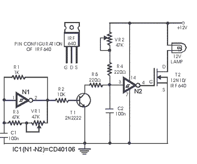
A PWM regulator LM2576, Lm2696 could be a solution.
https://www.ti.com/lit/ds/symlink/lm2576.pdf
https://www.ti.com/lit/ds/symlink/lm2596.pdf

---------------


-------------
9287467300_1351027304.gif

A more powerful FET like IRF3205 will be more eficient and withstand lot of current. Regulate power to control circuit with zener diode and series resister to work on high voltages.
 
actually the input is from 2 lead acid batteries that reaches up to 27Vdc

In that case I think you really should be using a switching regulator, not a linear regulator. Think: If the bulb consumes 21W, you have to dissipate at least that much in the linear regulator. It's going to get hot. A switching regulator circuit will probably cost no more than dealing with 21W+ of heat.

That said, do you want to know the very simplest solution?

Forget a regulator for powering a bulb, you don't need regulation. Just put a resistor in series with the bulb across the 24V. If the bulb is 21W at 12V, then its hot resistance is 6.9Ω. So, pick an 8Ω 25W (minimum) power resistor, bolt it to a big lump of metal, and wire it in series. Now, put a pan of water on that big lump of metal and make a cup of tea.
 
Last edited:
i am very thankful to all my good friends who replied and helped me. i at last get success and lit the bulb using switching regulator (LM2576) successfully with very less amount of heat dissipated. it lit the bulb with 28v input to it and fed 12v to bulb and it turned on normally as it is connected to a 12V battery. the problem was the over heat dissipation than the rated amount in LDO regulators and Transistors. the problem was only the heat sink in case of 2sd1047 transistors which is 100w power transistor and the voltage difference across it was of 16V (28V-12V) and current through it was 1.75A and hence power dissipation on it was P=16*1.75=28W which is very very much less than the rated 100w for the transistor ............. but still it blown out the transistor because of insufficient heatsink.
and LDO fail to lit because of large voltage difference as i used LM338t but it couldn't lit the bulb and couldn't pass the desired ampere of current as i applied 28v dc at its input and tried to drive the 21w load at the out put......................so with this large difference it was not able to conduct 1.75A of current .................. but WHY the same regulator charged my 12V PB-Acid batteries with and input of 35V at its input and out put was set to 14.9V thus with a difference of 35-14.9=20.1v and i conducted a current of 1.5A approximately and a power dissipated across it was P=20.1*1.5 = 30.15W ?????? it there any difference to pass current to drive a load and to charge a battery????? i can't understand this?
 

For driving the bulb, it is simply a case of the linear regulator (LM338T) shutting down due to the high, initial cold current (10A) that the bulb needs. Nothing to do with power dissipation at that point.

The switching regulator is clearly less sensitive to a high but transient cold current.

Glad you got it working, with a more efficient solution.
 

Rather than using just a series resistor, you could use a NTC ICL device (meaning a resistor with a negative temperature coefficient) to effectively null out the positive temperature coefficient of the filament. That should greatly decrease the inrush current, but cause minimal voltage drop once everything is hot.
 

For a simple solution, another bulb of same type and rating connected in series is enough!
 

Status
Not open for further replies.

Similar threads

Part and Inventory Search

Welcome to EDABoard.com

Sponsor

Back
Top