Continue to Site

Welcome to EDAboard.com

Welcome to our site! EDAboard.com is an international Electronics Discussion Forum focused on EDA software, circuits, schematics, books, theory, papers, asic, pld, 8051, DSP, Network, RF, Analog Design, PCB, Service Manuals... and a whole lot more! To participate you need to register. Registration is free. Click here to register now.

DC power through audio socket acting as amplifier 'power-on' switch via jack sleeve.

Status
Not open for further replies.

JonDrBrown

Newbie level 3
Joined
Sep 10, 2015
Messages
3
Helped
0
Reputation
0
Reaction score
0
Trophy points
1
Activity points
36
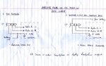
I am building a compact 2W stereo amplifier to work primarily with a smartphone audio output. To keep components to a minimum I have elected to have the unit power up only if there is a jack in the unit’s audio in socket. This is done by routing the 0 volts line from the battery to the amp via the sleeve connections on the jack socket – i.e. via the jack plug’s sleeve itself.
However, when connecting up a smartphone or laptop in this way, distortion arises which doesn’t happen when connecting the supply rail directly to the battery, or via a simple switch – which is what I’m trying to avoid. I suspect that this distortion occurs because a similar ‘auto-detect’ arrangement is in use in the source devices, i.e. smartphone / laptop, and that this is causing problems with disparate dc voltages / 0 volt levels.
Is this problem ‘created’ at the source device, or is it manifesting in the amplifier itself, and how, if at all, can I work around it?
 

I don't really know, so don't pay much attention to this answer - Is that set-up maybe creating a ground loop which could/would be the source of the distortion/noise?
If the amp and the laptop/'phone don't genuinely share a common ground point/reference that could be the problem you describe of disparate reference voltages between devices.

- - - Updated - - -

Maybe you can incorporate into the stereo amplifier circuit something along the lines of (but not specifically) an optocoupler/isolation amplifier (galvanic isolation)/etc to separate your power supply from the input signal of interest.
Or, and with the little I know, I might have looked into this point first - perhaps design some sort of compatible "enable" feature for the amp power supply when the audio jack is plugged in, or use a device that has this feature to do so, to avoid using the input signal audio jack being mixed in with the power supply 0V line (if that is your design).
if you're using a microcontroller or something, then it should be possible to configure the device to respond to an action (audio jack in), and be on standby/sleep/whatever it's called until that moment, a digital "enable" rather than an analogue version.
I really don't know what you're doing as you posted no schematic which makes it harder to offer (poor or inappropriate) advice, and no doubt am very wrong about this last point, but I suspect that unless it's a PLC (powerline communications)circuit ;), then mixing/crossing signal with power is "not recommended" if avoidable.
 
i don't understand what you are attempting. Your stereo jack fom your music source has a tip, ring and sleeve. The tip and ring are audio, the sleeve, the shield. When you plug it into your amplifier, you have a tag for the tip and a tag for the ring and a tag for the shield. It would be normal to connect the shield to the amplifier common. So where are you connecting your battery minus? . If your jack has two shield tags that are connected when the plug is in, it will work, just connect one to the amplifier minus and the other to the battery minus.
Another solution is to have a high gain amplifier that monitors the input(s) with low current consumption, so when it hears audio it switches the main amplifier on.
Frank
 
Which connector switch Sleeve?

You are wondering why DC ground current causes ground noise? with 50mOhm spec @1A or after aging?
or with low level signal or with inductive grounds and unshielded connector and signals?

Pls show your problem with photo of layout and scope trace. ( assuming 2.5 or 3.5 mm stereo with Gnd switch ) audiojack.jpg
 
Hello, thanks for your and others' replies.

I'll take the hint and post a diagram of what I'm after here.


jack0001medium.jpg


Basically, guitar effects pedals used to (possibly still do) power up using the presence of an input jack to route the 0 volt ('ground') line through its sleeve via two pins on the socket. No problems with noisy earths or distortion there then, but I've never plugged the phones socket from a laptop or mobile through such a device.

Thanks again for your interest and response, I'll endeavour to keep you posted. Regards, JonDr.
 

Attachments

  • jack0001small.jpg
    jack0001small.jpg
    63.3 KB · Views: 118

It looks as though you have a problem with contact resistance between the two tags and the sleeve. This would result in the change of current by the amplifier (on peaks in the audio) causing a voltage to change on the sleeve, and hence on the source and the coming back up the "live" audio feeds. You could try swopping over the wiring to the two sleeve tags, it might help. Try using switch cleaner, though it can attack some plastics.
Frank
 

Thanks Frank.

Lead and socket are brand new, though you have given me something to think about here. Also wondering if my problem is simply that the laptop or phone is using the same 'jack is in' detection method which is upsetting things at the amplifier end.

Will get hold of a guitar effects pedal...
 

Another point could be very high frequency oscillations due to the long earth path. What I am thinking is that the power - lead enters your PCB near the high power end. The earth lead is associated with input end so it would be taken of at this end along with the live audio inputs. Now you have changed the layout there could be some added impedance in the -lead. To check this, out see if any DC changes when you handle the input end. Better would be to use a CRO, use an earth closest to the input , look out for high frequency wave when the jack is in but there is no audio coming up the lead.
Frank
 

Status
Not open for further replies.

Part and Inventory Search

Welcome to EDABoard.com

Sponsor

Back
Top