ibnul7
Newbie level 6

- Joined
- Aug 23, 2013
- Messages
- 11
- Helped
- 0
- Reputation
- 0
- Reaction score
- 0
- Trophy points
- 1
- Activity points
- 95

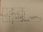
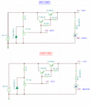
 Hey guys, I have designed and built this constant current/constant voltage power supply. I know it's a bit unconventional, but I've used a darlington pair transistor with a zener diode to regulate the voltage. The LM317 regulates the output current. The circuit does work very well with all sorts of loads. I now want to add short circuit protection, so I was just wondering how I would go about doing it. So far I''ve tried placing a PTC thermistor in series with the 16v Vin, and it works okay, except that the power transistor gets extremely hot (so I'm guessing it didn't really shut off the circuit). Any advice will be much appreciated. Thanks


