Continue to Site

Welcome to EDAboard.com

Welcome to our site! EDAboard.com is an international Electronics Discussion Forum focused on EDA software, circuits, schematics, books, theory, papers, asic, pld, 8051, DSP, Network, RF, Analog Design, PCB, Service Manuals... and a whole lot more! To participate you need to register. Registration is free. Click here to register now.

dc motor, to pull down or limit current

Status
Not open for further replies.

jorgechua

Newbie level 2
Joined
Jun 19, 2011
Messages
2
Helped
0
Reputation
0
Reaction score
0
Trophy points
1,281
Activity points
1,299
hi, i need help regarding DC motors...
i have a DC motor, its a power window motor actually. i will be supplying it with 12V lead acid battery. the problem is that it draws 2A current.
how do i pull down the current to at most 0.5A? do you guys know some current limiting circuits??
 

A DC electric motor draws a very high current when it is started and when it is stalled.
If you limit the current to the motor, then it might not start running and its torque will be reduced.
 

If the motor is rated at 2A, then the start-up current will very likely be much higher (for a short duration... several hundred milliseconds). As mister_rf mentioned, they pull more current at start-up... a.k.a. locked rotor current, which is Vsupply / (resistance of the motor windings). I concur, current-limiting the motor may cause you to not even get it started.

Why are you trying to current-limit it?
 

Between the 12V battery and the motor, you can use a series transistor (sometimes known as pass transistor) such as IGBT, preferably that can handle rating 2A or higher.

Vary the IGBT gate voltage by passing PWM signal (from a microcontroller) into a low-pass filter (to get equivalent DC voltage at IGBT gate) to vary the IGBT emitter current (from 2A to 0.5A) to the motor.
 

The preferred way to limit the current using a pass element (transistor, mosfet etc) is to use PWM that drives the element is either ON or OFF state, then using the duty cycle you can control the mean output voltage.
Using the gate (DC) voltage to control the amount of current provided from the pass element will reduce the efficiency and increase the consumption (heat) on the pass element because it will always be partially on with a considerable voltage drop across it.

Alex
 

If the motor is rated at 2A, then the start-up current will very likely be much higher (for a short duration... several hundred milliseconds). As mister_rf mentioned, they pull more current at start-up... a.k.a. locked rotor current, which is Vsupply / (resistance of the motor windings). I concur, current-limiting the motor may cause you to not even get it started.

Why are you trying to current-limit it?

thank you for the quick reply guys,
we're using the motor to rotate a frame so that it will always be facing the sun. every 15mins or so, we want it to move a little. we want to limit the current because at 12V, 2A, it's very fast. we can't measure the angle it moved with milliseconds and is very inaccurate.
 

Since the motor needs more current when stationary, you could send a long pulse to start it moving slightly. Then a series of shorter pulses to nudge it a little further.

To do this would require a tailor-made pulse generating circuit. It would turn a mosfet full-on and full-off.

You would need to experiment with the length of pulses and the number of pulses. Once you get the motor to move the correct distance, it should not need further adjustment. The sun moves at a constant rate across the sky.
 

we want it to move a little. we want to limit the current because at 12V, 2A, it's very fast. we can't measure the angle it moved with milliseconds and is very inaccurate.
To reduce the speed of a PM (permanent magnet) DC motor, you would want to supply it with a lower voltage rather than limiting the current. A speed variation ratio of up to 10:1 is usually achievable. I suggest to try with a variable voltage regulator, e.g. LM317. For a first test, a laboratory power supply or e.g. a 1.5V battery can be used.
 

thank you for the quick reply guys,
we're using the motor to rotate a frame so that it will always be facing the sun. every 15mins or so, we want it to move a little. we want to limit the current because at 12V, 2A, it's very fast. we can't measure the angle it moved with milliseconds and is very inaccurate.

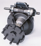
For solar tracking, the DC motor is going to be very, very inaccurate, I completely agree. You might investigate a gear-based reduction system. Look for something with a worm-gear, so you get a few thousand-to-1 reduction in revolutions. Then many turns of the motor will make only small changes in the platform's angle.

This is an industrial grade worm gear reduction box, but it'll give you a general idea of what they look like.
Gearbox.jpg

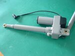
Alternately, you could set up your frame with a simple linear actuator and a center pivot. The linear actuator can extend or retract, which would push on the frame, causing it to rotate around the pivot. I believe what we used in college were linear actuators for aiming 8' home satellite dishes. It looked a bit like the example below, but had a longer stroke. Google linear actuator, or linear motor... that'll give you an idea of what they look like.

Linear_Actuator_for_Car_Door_D_Jack_649.jpg
 

Status
Not open for further replies.

Part and Inventory Search

Welcome to EDABoard.com

Sponsor

Back
Top