Continue to Site

Welcome to EDAboard.com

Welcome to our site! EDAboard.com is an international Electronics Discussion Forum focused on EDA software, circuits, schematics, books, theory, papers, asic, pld, 8051, DSP, Network, RF, Analog Design, PCB, Service Manuals... and a whole lot more! To participate you need to register. Registration is free. Click here to register now.

DC motor Speed Control help required

Status
Not open for further replies.

icarus1977

Newbie level 6
Joined
Jul 30, 2014
Messages
11
Helped
0
Reputation
0
Reaction score
0
Trophy points
1
Location
Walsall, West Midlands, United Kingdom
Activity points
94
DSC_0356.JPGDSC_0357.JPGHi all,

I hope this is in the correct section if not could a moderator please move it to the correct section...

Basically I have a small project I am working on, but it's been a few years and I am a bit rusty on my basic principles etc

I have built and have running a lure machine, for dragging a dummy bunny to aid in the training of a bird of prey...

But I need to slow the speed down, at one point it was clocked at 5,600 RPM before we fitted the pulleys so speed may have been increased further, I am happy with the speed except for when I wish to load the spool in which case it's running too fast and following a snag in the line resulted in the spool flying dangerously fast in my direction...

So I was trying to work out a way to slow the motor down, without having to use a mechanical solution...

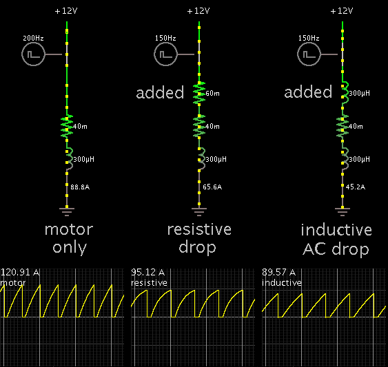
The motor I am using is a Starter motor (part number is 25092D - M35G), it's running off a 12V Motor Bike Battery.

I have approximated that she is pulling around 40A but are unable to test correctly as my meter is not up to it...

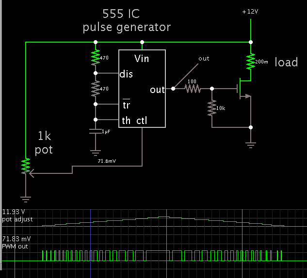
How would I best control the speed of it, would a PWM circuit correctly control the circuit or would it soon burn it out, I thought of a rheostat but it would need to be bulky to handle that sort of current, same as if I used a potential divider circuit...

Any help on this would be greatly appreciated...

- - - Updated - - -

Just found out the following information on the starter motor I am using, hope it's correct...

25092D M35G-12V-0.8Kw STARTER MOTOR AMBASSADOR PETROL 1.5 HM PLUS

So it looks like it's pulling 67A not what I initially thought of 40A...

- - - Updated - - -

So it's a series wound dc motor, so am I right in thinking that I could use a mosfet to control the motor speed using a voltage level shifter on the gate. As I believe a mosfet is not concerned about the size of current passing through it...

Or would a H circuit using transistors work better?
 
Last edited:

If you are rusty then buy it https://www.ebay.ca/itm/12-40V-100A-1200W-DC-Motor-Speed-Control-PWM-Controller-/140357609275

But you need a really low RdsOn Mosfet with a 20kHz PWM ( ( so you can't hear it) Variable duty cycle with a remote Pot.

100A switch is needed or more in case of a stalled motor (twang)

I would outline a design, but not worth your headache, if you are rusty.
Thermal design, Short circuit design, high current design, low switching loss and low noise design.

Keep the welding cables twisted to reduce EMI interference.
 

I'm wondering if your DC motor has 2 brushes? Not that I know everything about starter motors, but maybe its windings are switched in, one at a time, in sequence. This would create ramp waves, which is like an AC component.

I think it's worth trying, to fabricate a coil, which will introduce an inductive drop.

A choke, in other words.

The coil might only need to be less than 1 mH, since you are drawing heavy current.


A suitable wire is 6 to 8 gauge enameled wire. This size should be safe for carrying 50A or so (non-continuous use).

You would wrap it around a metal core, same as if you were making a transformer. A certain number of turns. There are online calculators to tell you. You would need to experiment.

I'm just talking theory and estimates here.

As an alternative, you can insert a small resistive drop. My simulation has .06 ohms. However it needs to dissipate several hundred watts. This is the case whether you install a resistor, or a mosfet / transistor.
 

Hi SunnySkyguy,

I'd love to see your outline and get the brain cells working again, as it's been a while but I still have all the necessary equipment here and pcb etching equipment etc...

It's a side of things I miss, so would love to get back to basics and start from scratch and design and build it with help from yourself and any other members on this forum...


Would this be suitable?

NTMFS4846: Power MOSFET 30V 100A 3.4 mOhm Single N-Channel SO-8FL

- - - Updated - - -

Ok what I am thinking is a remote push button start, that can be up to 10 feet away from the Lure Machine, with a variable speed controller mounted onto the lure machine which is then pre-set to the desired speed.

Reason for the remote push start is so that the bird cannot anticipate when the dummy bunny is about to be realised...

How is the best way to break the circuit down in to it's individual separate components...

What do we require?

Over current protection to protect the motor, but the line we are using currently has a 100lb breaking strain so if it get snagged the line automatically snaps so in theory second I release the push button the motor should stop if I see any sign of an issue...

As it's a series wound motor with high starting torque it has the greatest no load speed, so should the line break and I not spot it in time the motor will just increase in speed which could potentially damage the motor... so I need to also consider a way to protect the motor should this happen...
 
Last edited by a moderator:

So I have been having a think about this, would I be ok using a NE555 to produce a variable PWM output that is then connected to the gate of a MOSFET possibly via a NPN transistor to prevent accidently switching on of the MOSFET...

Would this work, I have got some basic hand drawn sketches but they are very messy so will attempt to tidy them up a bit before posting...

I no longer have any working CAD software to produce a tidy drawing, but found this on line and tweaked it to sort my own needs...

PWM.jpg
 

As I have never done any projects before involving a MOSFET, do I treat it the same as I would a transistor?

would I also incorporate overload and short circuit protection around it, or just use a fuse?

Also would I be safer to use more than one MOSFET with the source and drain connected together?
 

Mosfets have what is called an insulated gate. It is easy to puncture by exposure to high voltage. This makes it easy to ruin a mosfet.

Your project is liable to create a hazardous environment for mosfets. Switching high current (PWM) through a motor generates high voltage spikes, perhaps even sparks. (Even in normal operation you may see sparks appear at the brushes, in a conventional DC motor.)

Static charge can ruin a mosfet. Since we can't predict about static build up in your circuitry, you ought to guard against it.

Expect to burn up a few mosfets in the design process.

You may be better off using a high power transistor.

If necessary you can parallel them. This requires some effort in carefully adjusting operation in each device, so neither has greater burden.
 

Hence the reason I am asking for help, just never used a Mosfet before...

How would you control the speed, the option on Ebay is very expensive with Delivery charges etc...

The only high current switching I have ever done is with Big Contactors and coils, but never electronically

Most I have ever had to switch was 3A nothing higher...
 

hi, just a suggestion.

you are trying to switch 67A, I expect this is the start current,

so you are going to need a device with very low on resistance.
A DC to DC SSD relay of the right spec would do the job.

may be an SSRDC100V40A ssd relay on a heat sink would be ok.
see SSRDC100V40A. data sheet

all you would then need is a 555 timer wired for adjustable
PULSE WIDTH MODULATION to drive the SSD relay.
the on/off time spec for this relay is 0.5ms, surge currents 160A, load currents 40A
 

The aim is to use rugged components. A power transistor is more likely to stand up to abuse than a mosfet.

If you use a transistor, then a 555 IC will lack the power to drive it. You would need a middleman transistor/mosfet.

Just one more idea here, which may be the easiest yet...

Your aim is to reduce motor speed when you load the spool. Suppose you were to use a 6V battery for that purpose?

I imagine it will draw about half the amperage. That means 1/4 the wattage. I cannot predict whether it will run at half the orignal speed, or one quarter the speed.

You would need to install the correct switching arrangement, of course, to avoid conflict with the 12V battery.

A suitable 6V battery might be available at a motorcycle shop.
 

Using transistors for switching 40a-67a is possible but you will have to have a few in parallel or otherwise you will have to buy a very big transistor to get the 67a. The vcesat of transistors also means that you power will be wasted and the transistors will get hot.

Transistors are not self protecting like fets and also when they are in parallel the on/off times may be slow you will also need current sharing resistors too.

For your sort of application high power switching fets will be better.

Dc-dc ssd relays uses these fets to switch large currents with no moving parts.

They can be opto isolated or dc logic level driven.
They use them in cars these day to operate all sort of things driven from the cars computer.

Logic power fets are also quite easy to use as well and you could put them in parallel like transistor .

Yes if you want to just reduce the speed and not worry about the torque of the motor it may be ok if it turns.

Pulse proportional control will enable better adjustment of speed. that’s what they use on electric drills.
 
Last edited by a moderator:

Thanks for that, I am thinking of using a LM3524 in line with a mosfet driver in a half bridge configuration... but then I just spotted your additions to the thread... some more food for thought...

The 6v battery is a novel idea...

I did initially think 12v dc coil and contactor for switching the load, but not for speed control... no ever thought of a SSD...

Which is the best option?
 

In the back of my mind I've been thinking...

12V times 67A is over 720 W.
720 W is one horsepower. You've got a horse pulling a rabbit.

Many people would say 'that must be some rabbit.'

Here is my theory. I think you could get by on 1/2 horse or less. You could reduce power to the starter motor by reducing voltage. This will reduce its speed. Then to preserve speed, install a larger pulley.

This will draw less current when you use the system for its primary purpose.

Then for loading the spool you may only need a few amperes. This adds options to the list. For instance a buck converter has not yet been mentioned. There is a chance it would work better than PWM which you are considering.

that's correct its a large dc motor may be its a starter motor.
but he did say that he thinks that the current when measured was 40A.
and yes maybe a small geared motor could be use or even a stepper motor i don't know but, may be the person needs the torque provided by the motor he has chosen. i can only assume that when he lets out the length of rope it may get caught up and he needs the power to pull it. it would be nice to know the speed of the pulled line in Mtrs/sec, or ft/sec
 
Last edited:

I have no idea how fast it is running, we tried to clock it and found it running at 5,600rpm..

Most of the lures machine's run at roughly 43Mph, length of braid plus weight of dummy bunny and the obstacles it needs to run round to simulate a rabbit running, I believe we need max power and torque...

But for training and loading the spool I need it to be variable speed...

When I tried to measure the current, my meter was not man enough so we tried a tong tester but not sure if they work well enough on DC but it was measuring 40 amps at one point, but when we put it on full power it hit a lot higher current...

12V times 67A is over 720 W.
720 W is one horsepower. You've got a horse pulling a rabbit.

Never thought of it in that sense...

I will measure the pulleys and maybe we could work out the speed she is running at...

Getting myself a tad lost, just not sure how best to control it...

Thought this was going to be a straight forward simple little project
 

Yes, if you notice the motor speed slowing due to obstacles, etc., then it means you need all that power.

Here is a simulation to illustrate the PWM solution.

The 555 timer IC has a 'control' pin, at which a change in voltage varies the duty cycle.

The potentiometer was dialed up and down. The pulses get longer and shorter.


At least the theory of operation is that simple.
 
Wow thanks for that, think I may have an alternative solution never spotted your reply till just sorry...

I have a LM3524 that is giving me a variable pwm of 10KHz on output pin 13, basic circuit is attached as my schematic software is no longer functional I am having to resort to alternative methods... LM3524.jpg

So what I was thinking of doing is running a couple of IRF4905 (rated at 74A), hopfully this should provide a workable solution... the frequency being used is just outside the hearing range for a bird of prey...
 

Let's get back to basics in the design.

Assumptions:
- steel Rope with 100 lb Rated load, mass of bunny , pulley ratio, N and possible snag load of Fs
- 1HP 12V motor > 5400 RPM max
- max bunny speed of 40 MPH

What is maximum average torque , hence average current of motor?
What is acceleration , based on max Force or avg. motor current ?
What is optimal pulley ratio for RPM for 40MPH and max. acceleration to prevent overload on motor drivers and rope?
What is stop force due to friction, Fd? Based on de-acceleration, a

f=m * a


You will want to include a current and RPM sensor in your design to regulate the PWM. The MOSFET should be rated for stalled motor current or have safety cutoff.

Current sense can be simple 50-100mV shunt of from power cable drop, calibrated from a test for resistance with known current.
RPM can be measured with a HALL Sensor on shaft of spool with notch or tooth to trigger a one-shot, V=k*RPM

Inductive load dump must be diode clamped to handle max motor current at inductance E= 1/2L I^2 [Joules]. Reverse recovery time limits PWM rate.

Budget including PWB and parts & heatsink may exceed cost of eBay motor controller.


Ready to complete design Spec? Add more assumptions, fill in blanks. I'm not clear how you stop this design with inertia and drag.
 

I have a LM3524 that is giving me a variable pwm of 10KHz on output pin 13

This IC is popular in building switched-coil power supplies. A search will turn up several forum discussions about projects which use it.

So what I was thinking of doing is running a couple of IRF4905 (rated at 74A), hopfully this should provide a workable solution... the frequency being used is just outside the hearing range for a bird of prey...

This can work.
You may encounter high-voltage spikes. This is common when switching high current through inductors.
Therefore you can expect to need to cure the spikes by installing snubbing networks.

The motor contains coils. When you apply pulsed DC, you create something that behaves like a buck converter, or at least has some of its characteristics.
 

Status
Not open for further replies.

Part and Inventory Search

Welcome to EDABoard.com

Sponsor

Back
Top