Continue to Site

Welcome to EDAboard.com

Welcome to our site! EDAboard.com is an international Electronics Discussion Forum focused on EDA software, circuits, schematics, books, theory, papers, asic, pld, 8051, DSP, Network, RF, Analog Design, PCB, Service Manuals... and a whole lot more! To participate you need to register. Registration is free. Click here to register now.

DC Motor PWM Circuit Doesn't Work When Controller And Motor Share Voltage Source?

Status
Not open for further replies.

silloprice

Newbie level 4
Joined
Jun 4, 2021
Messages
6
Helped
0
Reputation
0
Reaction score
0
Trophy points
1
Activity points
42
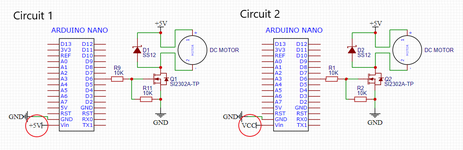
I've been experimenting with DC motor control using PWM from an Arduino Nano. Something I've noticed is that the circuit only works when the motor and controller use different voltage sources (see circuit 2). e.g. when the Arduino is powered by its USB port, and the motor is powered by my bench power supply. I understand the need for a common ground between the two parts of the circuit, but why can't they also share the same +5V source? (as shown in circuit 1).

**broken link removed**

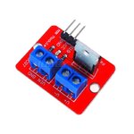
I've also found this to be the case when using a MOS module as shown in the image below. If VCC and VIN are from the same supply, it doesn't work :/

**broken link removed**

Thank you in advance for any responses!

Charlie
 
Last edited by a moderator:

It should not be a problem but the attachments are not opening. Did you try to extensively decouple the motor from the power supply?

Common ground is also not strictly needed (if you use an opto coupler, for example), but just a small resistor, a small inductor and a decent filter capacitor should be sufficient to uncouple the arduino.
 
Hi,

Attachments: There is a timeout from uploading file to sending the post.
Please generate a new post with new attachments.

***
The described problem seems to be caused by current overload. But we have no specification about currents.

Klaus
 
Thank you for your responses. I have attached the images to this message.

The motor in question is a Syma X5C DC quadcopter motor which draws 1.5-2A with props attached.

It should not be a problem but the attachments are not opening. Did you try to extensively decouple the motor from the power supply?

Common ground is also not strictly needed (if you use an opto coupler, for example), but just a small resistor, a small inductor and a decent filter capacitor should be sufficient to uncouple the arduino.

In the DC motor circuits I've looked at, I've never seen people go to such efforts to decouple components from each other. I'm a first year undergrad in electromechanical engineering and I thought DC motor control would be the easiest thing to get started with! :LOL:
 

Attachments

  • diagrams.png
    diagrams.png
    45.3 KB · Views: 178
  • irf520-mosfet-driver-module.jpg
    irf520-mosfet-driver-module.jpg
    63.4 KB · Views: 163

Hi,

it could be easy. But it may fail.
It´s nothing mystic. One can calculate it.

A USB port is able to supply 0.5A. If your circuit draws more than this - even for microseconds - then it may fail.

But without knowing the motor current ... it makes no sense to discuss...

Klaus
 
Hi,

it could be easy. But it may fail.
It´s nothing mystic. One can calculate it.

A USB port is able to supply 0.5A. If your circuit draws more than this - even for microseconds - then it may fail.

But without knowing the motor current ... it makes no sense to discuss...

Klaus
Thanks for your response. I'm not powering the motor by USB or from a pin on the Arduino. The motor is powered by my 10A bench power supply. When I try powering the microcontroller from this same power supply it doesn't work, but when I power the microcontroller separately (by USB), it does work.
 

Hi,

I can only help, if you tell me about the motor current.
Also please post a photo (filesize of 100kByte should be sufficient) of the complete wiring.

Klaus
 

It might be less about current than its "chopping". The motor -drive- might be what needs a separation of signal / data supply and ground from electromechanical. Have you put a 'scope to the supply to see how filthy?
 
Hi,

I missed the motor current information, sorry.

now you I see four of them... do you want all of them connected?
So we talk about 8A...and even more at startup and even more at the pulses?

Confusing: the schematic and the PCB is totally different in wiring and part values. Show the truth only! Otherwise you risk to confuse us and yourself.

****
Issues of your wiring:
* breadboard --> is not suitable for high current and pulsed current
* thin cables
* no bulk capacitor
* current flow (wiring order)
* GND loop

So it´s no surprise that it fails.

*****
Wiring, just one motor:
* disconnect everything except the motor.

* power supply: red and blue directly to the screw terminal of the driver PCB. In parallel install a 1000uF capacitor (short wires) to the screw terminal.
If by hand: install a 1uF ceramics in parallel to the 1000uF capacitor. Best directly soldered on the PCB.

* if not wired a t the motor: you need a fast recovery diode in parallel to the motor as shown in your schematic.

* you don´t need the 10k series resistor as shown in your schematic.

* Arduino: Use three wires from the 3 pin terminal of the driver PCB and wire them to the arduino.
(No other wires, no additional GND, don´t use the breadboard bus) Install a 100uF bulk low ESR capacitor at VCC and GND of the arduino.

Klaus
 

    silloprice

    Points: 2
    Helpful Answer Positive Rating
Hi,

I missed the motor current information, sorry.

now you I see four of them... do you want all of them connected?
So we talk about 8A...and even more at startup and even more at the pulses?

Confusing: the schematic and the PCB is totally different in wiring and part values. Show the truth only! Otherwise you risk to confuse us and yourself.

****
Issues of your wiring:
* breadboard --> is not suitable for high current and pulsed current
* thin cables
* no bulk capacitor
* current flow (wiring order)
* GND loop

So it´s no surprise that it fails.

*****
Wiring, just one motor:
* disconnect everything except the motor.

* power supply: red and blue directly to the screw terminal of the driver PCB. In parallel install a 1000uF capacitor (short wires) to the screw terminal.
If by hand: install a 1uF ceramics in parallel to the 1000uF capacitor. Best directly soldered on the PCB.

* if not wired a t the motor: you need a fast recovery diode in parallel to the motor as shown in your schematic.

* you don´t need the 10k series resistor as shown in your schematic.

* Arduino: Use three wires from the 3 pin terminal of the driver PCB and wire them to the arduino.
(No other wires, no additional GND, don´t use the breadboard bus) Install a 100uF bulk low ESR capacitor at VCC and GND of the arduino.

Klaus
This is a great help. I've got it working now. Thank you for your suggestions.

Charlie
 

Status
Not open for further replies.

Part and Inventory Search

Welcome to EDABoard.com

Sponsor

Back
Top