Continue to Site

Welcome to EDAboard.com

Welcome to our site! EDAboard.com is an international Electronics Discussion Forum focused on EDA software, circuits, schematics, books, theory, papers, asic, pld, 8051, DSP, Network, RF, Analog Design, PCB, Service Manuals... and a whole lot more! To participate you need to register. Registration is free. Click here to register now.

[SOLVED] DC Motor Interfacing using 8051

Status
Not open for further replies.

gauravkothari23

Advanced Member level 2
Joined
Mar 21, 2015
Messages
640
Helped
5
Reputation
10
Reaction score
4
Trophy points
1,298
Activity points
6,922
Hi all.
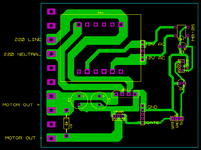
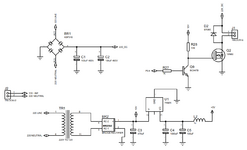
I am trying to interface a 380V DC 180 Watts DC Motor using 8051 controller. (Circuit Diagram Attached)
As per the circuit, the problem what i am facing is, As soon as i connect the system to 220V AC line, sometimes the bridge BR1 (KBP310) and Everytime 19N60 mosfet gets busted.
Can anybody please help me what the problem is with the circuit. Even checked for the shorts and Missing tracks, but everythin
i am going to use PWM to drive the motor.
Initially for testing i have just placed an LED with 100K 2 watts Resistor at the output to check it i get a proper output.
--- Updated ---

I Made a small Test, Using a 220V to 24V Transformer.
I Removed TR1 which is converting 220V AC to 12V AC and powering the controller.
and applied 24V AC to BR1 which is Powering the Motor.
and applied 12V DC from 220V to 12V DC Adaptor at the input of BR2 Pin AC-1 and AC-2. then the system is working perfectly, but the same when i connect to 220V AC, 19N60 Mosfet Explodes.
 

Attachments

  • 220DC Motor Drive.png
    220DC Motor Drive.png
    86.7 KB · Views: 137
Last edited:

Solution
Hi,

I guess you talk about
* conduction loss
only. But there additionally is
* switching loss.
It depends on switching frequency, load current and
Switch_on_time and switch_off_time.
This is the time when drain current flows, but voltage is not saturated (completely ON or OFF).
The higher the collector resistor value, the higher the switch_on_time, the higher the switching loss.

Your 19N60 Mosfet has a thermal resistance of about 40K/W without heatsink. This means you must not dissipate more than 3W.
When continously ON this means the current must not be higher than 2.8A (@380mOhm).

Switching a resistive load of 300 Ohm load at 300V gives 1A full current. And causes 0.38W.
But during switch ON there is tye worst case when the...
Hi,

Please show the PCB layout.

Klaus

Issues I see:
* The Diode SR360 is not sepeicified for 300V
* the 10k pullup for the gate makes switch_on rather slow and thus generates a lot of dissipated power. In detail it depends on switching frequency.
There are dedicated MOSFET driver ICs.
* rectified 230V given to a capacitor may generate more than 300V DC
* rectified 12V from a small transformer given to a capacitor may generate more than 20V DC
* L2 makes no sense
 
Last edited:

i Have Attached the PCB Layout
--- Updated ---

Hi,

Please show the PCB layout.

Klaus

Issues I see:
* The Diode SR360 is not sepeicified for 300V
* the 10k pullup for the gate makes switch_on rather slow and thus generates a lot of dissipated power. In detail it depends on switching frequency.
There are dedicated MOSFET driver ICs.
* rectified 230V given to a capacitor may generate more than 300V DC
* rectified 12V from a small transformer given to a capacitor may generate more than 20V DC
* L2 makes no sense

for SR360, do i need higher voltage diode then the voltage supplied to motor, as it is a flyback diode.
switching frequency is aroung 1 Khz
Due to cost effective, i have to drive it using transistors.
Recified 230v, i need around 350V to drive the motor.
Retified 12V, it gives me 15V DC
L2 is the Inductor.
--- Updated ---

Instead of SR360, can i use 1n4007 Diode as it is rated for 1000V
--- Updated ---

now i guess, the SR360 itself is getting dead first due to higher voltage then rated, due to which there is a lot of stress on Mosfet, which also gets killed.
Let me check with some high rating diode.
 

Attachments

  • 220DC Motor Drive pcb.png
    220DC Motor Drive pcb.png
    75.1 KB · Views: 96
Last edited:

Hi,

Did you read the diode datasheet?
It is rated for 60V only ... while it needs to widthstand more than 300V in your circuit.

The PCB layout is just a connection of parts ... no GND plane, no good supply decoupling, no low inductance layout.

Klaus
 

I agree that low diode voltage rating is a sufficient cause for circuit damage. But weak driver may still cause high power dissipation of the MOSFET, even at 1 kHz only. You should definitely move to a two- or three-transistor push-pull driver. Also use a fast recovery high voltage diode instead of 1N4007.

PCB does not 100% fit the schematic, e.g. no 12V supply for the gate driver connected.
--- Updated ---

A possible disadvantage of the circuit is that the controller circuit is residing at a high voltage potential, all circuit parts are carrying hazardous contact voltage and you can't connect e.g. a programmer without high voltage isolation. The ground symbols are indicating a floating HV ground.
 
Last edited:

Thanks all, i have tested the circuit initially using UF4007 Diode instead of SR360, it works.
But again i am facing other issue,
The mosfet what i am using is 19N60, and currently the load attached to the mosfet is a LED with 100K Resistor.
Many a times, i can say 4 out of 10, when i power up the circuit, at initial power up, the mosfet Drain and Source pin get shorted and the mosfet stops working.
So i tried changing the mosfet to 20N60, but again the same problem arises.
But if i connect the motor, everytime the mosfet Drain and Source pin gets Shorted.
i Tried with IXFH28N60. where the things work perfect.
can you please suggest what the issue is with 19N60 and 20N60.
 

Certainly an avalanched back-diode will be a source
of instantaneous current once the FET turns on,
unlike the leisurely inductor current ramp you
probably have planned on for the motor load.
That means PWM is not producing a controlled
switch current in the MOSFET, but whatever the
now-probably-shorted diode can pass to its drain.

Maybe you want to step back a little and start
driving just the power stage with a sig gen source,
and see what survives with a simple RL load that
emulates the stalled motor "close enough". Keep
substituting reasonably rated parts there until it
survives, and then see what breaks next.
 

LED and the resistor are the only load
Then exceeding the current rating isn't the cause if the MOSFET is rated at 19+ Amps and you are only passing a few mA.
Somehow you are exceeding the voltage rating and my guess is it isn't Drain to Source but something wrong with the gate drive signal. Please do as Klaus asks and show a photograph.

Brian.
 

I Have attached PCB Images,
The mosfet currently used is IXFH28N60 which works perfect with LED and Motor
 

Attachments

  • WhatsApp Image 2021-06-18 at 2.14.37 PM.jpeg
    WhatsApp Image 2021-06-18 at 2.14.37 PM.jpeg
    98.9 KB · Views: 87
  • WhatsApp Image 2021-06-18 at 2.14.37 PM (1).jpeg
    WhatsApp Image 2021-06-18 at 2.14.37 PM (1).jpeg
    83.7 KB · Views: 86
  • WhatsApp Image 2021-06-18 at 2.14.37 PM (2).jpeg
    WhatsApp Image 2021-06-18 at 2.14.37 PM (2).jpeg
    78.8 KB · Views: 88

Then exceeding the current rating isn't the cause if the MOSFET is rated at 19+ Amps and you are only passing a few mA.
Somehow you are exceeding the voltage rating and my guess is it isn't Drain to Source but something wrong with the gate drive signal. Please do as Klaus asks and show a photograph.

Brian.
The Power Supply PCB is Hand Made using Toner Transfer Method.
 

LED and the resistor are the only load
Not true, the diode is in parallel to that connectorized
"load" and it acts like a zener (avalanche) diode when
supply exceeds 60V or so.

LED and resistor might be the only -intentional- load.
But you know what they say about "good intentions"
(or maybe not).

Your LED / resistor string has no need for the back
diode so you could remove it for purposes of testing
the MOSFET and its drive, alone. You only need the
back diode when the load is inductive.
yes, agreed, but the flyback diode i am using is UF4007 which is 1000V rated
But when i connect the Inductive load of Motor, the Mosfet everytime gets damaged and drain and source gets shorted.
 

Presumed you are still using the 10k impedance gate driver circuit shown in post #1, I'm not surprised about MOSFET damage with motor load.
 

Presumed you are still using the 10k impedance gate driver circuit shown in post #1, I'm not surprised about MOSFET damage with motor load.
Thanks for reply.
What resistor has to be used, should I need to increase the resistor value
--- Updated ---

Presumed you are still using the 10k impedance gate driver circuit shown in post #1, I'm not surprised about MOSFET damage with motor load.
Which parameter in datasheet will provide me this information.
 
Last edited:

Think of the gate to source capacitance of the MOSFET. For the 19N60 it can be as much as 3.6nF. During the switching cycles the charge on the gate will discharge through Q9 but it has to charge through R28. Almost certainly what is happening is the MOSFET is stuck in partial conduction because the gate voltage doesn't have enough time to rise high enough to bring it into full conduction. The result is high power dissipation. You must lower the value of R28 to (a guess) a few hundred Ohms.
If you have an oscilloscope, it would be interesting to see the gate drive waveform.

I still can't understand why a drain load consisting of ONLY a 100K resistor and LED can possibly allow enough current to flow to cause damage though.

Personally, I would consider adding some surge limitation on the AC input as well.

Brian.
 

MOSFET gate driving -

https://toshiba.semicon-storage.com/info/docget.jsp?did=59460 gate drive R


The gate drive R accomplishes two primary considerations

1) "Kills" inductive effects in gate circuit which could otherwise create large transients and
rupture gate oxide of MOSFET.

2) Limits max current of driver current supply


Regards, Dana.
 

Hi,

Why a Mosfet gets damaged:
* overcurrent: here unlikely because of high impedance load
* overvoltage - even short peaks: unlikely with the given load. Maybe it is a wirewound resistor. Maybe peaks from the input side, but with the guven informations I see no reason
* power dissipation, heat: unlikely with the given load.

Thus I guees there is something we don't know.
The schematic definitely does not match the PCB ... It's confusig. I recommend to rectify this.
Maybe the gate drive voltage is too high/low. Maybe there is coupling from drain to gate,
--> what's the DVM measured value of the 12V DC and the 5V DC
--> How do scope picture look: gate-source and drain-source?

Klaus
 

Status
Not open for further replies.

Part and Inventory Search

Welcome to EDABoard.com

Sponsor

Back
Top