Continue to Site

Welcome to EDAboard.com

Welcome to our site! EDAboard.com is an international Electronics Discussion Forum focused on EDA software, circuits, schematics, books, theory, papers, asic, pld, 8051, DSP, Network, RF, Analog Design, PCB, Service Manuals... and a whole lot more! To participate you need to register. Registration is free. Click here to register now.

DC motor control

Status
Not open for further replies.

Barrywan

Newbie level 6
Joined
Feb 6, 2023
Messages
11
Helped
0
Reputation
0
Reaction score
0
Trophy points
1
Activity points
87
I may be in the wrong place as any other questions on this are way over my head. But, here goes"

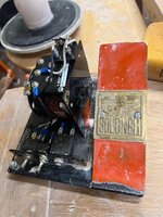
I want to use a 90 volt permanent magnet DC motor and control it with either a pedal or a dial. This is for a potter's wheel. This wheel originally had a big reostat (5A) built into a pedal. I got it with neither the motor of the pedal. The maker of the wheel said that this analog system made more consistent power, easily to adjust speed and made it quieter than an electronic controller. The replacement reostat is now $800,,,so, any thoughts?
Thanks,
Barry
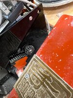
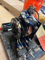
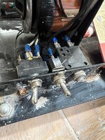
This is wheel in question:
This is a link to a solid state wheel system.
 

Those prices are extortionate!
The optimum control system depends on the motor specification. See if there is an identification plate on the motor body or a part number and let us know it or better still attach a photograph with the ID visible in it. My first through is to build a PWM controller, it isn't difficult and is far more efficient and certainly far cheaper than a rheostat but no all motors work well when driven with PWM signals.

Brian.
 

I agree with Brian, those prices are absurd. $15 for a fuse???

They don’t rate rheostats in amps, they’re rated in watts, so I’m not sure what that 5A rating means. Regardless, I would look elsewhere for the parts; obviously this potter’s supply company thinks you’re an idiot and will take complete advantage of you. Look at Grainger.com, or just do an internet search for DC motor control.

You haven’t given us any information about the motor requirements.
 

Those prices are extortionate!
The optimum control system depends on the motor specification. See if there is an identification plate on the motor body or a part number and let us know it or better still attach a photograph with the ID visible in it. My first through is to build a PWM controller, it isn't difficult and is far more efficient and certainly far cheaper than a rheostat but no all motors work well when driven with PWM signals.

Brian.
OK, so no motor yet. I will get a 1/4 -1/3 hp, like this" https://www.amazon.com/dp/B007L7UNLQ?ref_=cm_sw_r_apin_dp_9TZFAMXKKVSWYR9P0SWS&th=1
This is a replacement currently used by others.
 

Hi,

the device of post#6 won´t work, because it´s AC output. You need DC output.

I guess there are adjustable DC power supplies.
Then you don´t have the PWM noise problem.

Or you go two stages: One fixed 100V DC supply and an adjustable step-down (buck) converter (module).

Both together could be below 50$.

Klaus
 

Rather than rheostat, you could use a MOSFET with a potentiometer to control the gate voltage. Alternatively, you could use a magnetic amplifier. I'll post a circuit of one later. I need to do other things at the moment.
 

Hi,

the device of post#6 won´t work, because it´s AC output. You need DC output.

I guess there are adjustable DC power supplies.
Then you don´t have the PWM noise problem.

Or you go two stages: One fixed 100V DC supply and an adjustable step-down (buck) converter (module).

Both together could be below 50$.

Klaus
dc power supply, OK. A buck converter, as seen on at Amazon for $5-10? All new to me but I am willing to try it.
--- Updated ---

Rather than rheostat, you could use a MOSFET with a potentiometer to control the gate voltage. Alternatively, you could use a magnetic amplifier. I'll post a circuit of one later. I need to do other things at the moment.,
Great, MOSFET
I am not in a big hurry, and there seem to be several options.
This from a post on wheels that this motor is for. It addresses an issue with electronic controllers as opposed to the analog ones:

The Soldner controller is an expensive item because the controller
part of the foot pedal is a variable autotransformer (Variac) that
puts out a smooth voltage all the way from zero to max.
It is AC at that point so the AC is fed through a bridge rectifier
and then filtered in some more electrical parts so the net result is
a DC voltage to the motor that varies smoothly from zero to max. And
oh yes there is some kind of gearing between the foot pedal and the
Variac since it takes a full 340 degree rotation of the Variac shaft
to work it. Now you see why it is so big and heavy and expensive. The
technology is very old and low tech.
\Recent wheels try to get the smoothly variable DC with electronics
but seldom succeed as well especially at low speed. Modern
controllers have feedback so if you try to slow the wheel down by
putting more drag on the wheel the controller ups the voltage to the
motor to give more torque. A Soldner does not do that - you have to
do it by stepping on the pedal a little more. This becomes automatic
as you learn to use it and is never a problem for a person who gets
used to it.
--- Updated ---

This what is what the current pedal/controller is. The builder did not want an electronic controller.
 

Attachments

  • 327155884_695598512260031_4922973861985000808_n.jpg
    327155884_695598512260031_4922973861985000808_n.jpg
    1.6 MB · Views: 97
  • 327965184_1701947093534284_3027444898307239617_n.jpg
    327965184_1701947093534284_3027444898307239617_n.jpg
    1.1 MB · Views: 80
  • 328199991_3407190309496150_3970325351758126235_n.jpg
    328199991_3407190309496150_3970325351758126235_n.jpg
    1.3 MB · Views: 103
  • 327655261_5968998216470027_4339471152909526459_n.jpg
    327655261_5968998216470027_4339471152909526459_n.jpg
    1.2 MB · Views: 89
Last edited:

A thought - with the advent of E-bikes, there's a lot of off-the-shelf stuff available now at very competitive prices. You could explore repurposing some of this for your needs.
 
I found several of these variable transformers (same model)
Hi,

the device of post#6 won´t work, because it´s AC output. You need DC output.

I guess there are adjustable DC power supplies.
Then you don´t have the PWM noise problem.

Or you go two stages: One fixed 100V DC supply and an adjustable step-down (buck) converter (module).

Both together could be below 50$.

Klaus
So a bridge rectifier will turn the AC to DC?


for about $60-90, used but working,,,it is the same as the one used in the pedal. They are indeed about $750 if new.
 

I agree with Brian, those prices are absurd. $15 for a fuse???

They don’t rate rheostats in amps, they’re rated in watts, so I’m not sure what that 5A rating means. Regardless, I would look elsewhere for the parts; obviously this potter’s supply company thinks you’re an idiot and will take complete advantage of you. Look at Grainger.com, or just do an internet search for DC motor control.

You haven’t given us any information about the motor requirements.
 

On this rheostat there is an A, which means 4.5 amps? I see no watts listed.

Now, could a bridge rectifier be mounted anywhere between the motor and the rheostat?

The rheostat ac output,to the recitifier and anything else before the 90 v motor connection?

And options to limit output to motor, is there a reason to not just put a physical/mechanical stop on the rotator?, goes to 90 v and is stopped/blocked there?
 

Barry, Thanks for correcting me. As I said at the top; "I may be in the wrong place as any other questions on this are way over my head. But, here goes"

Does a rheostat and an autotransformer do the same thing but do so differently? They are both variable transformers? Will they both control a dc motor if the current is changed from AC to DC?

It seems as if the autotransformer is a better (more energy efficient option)

Apparently I am looking for an autotransformer in any case.
 

A rheostat is a variable resistor, quite different from a variable transformer. Autotransformer is much more efficient.
 

Hi,

An autotransformer output is AC.
But you need DC.
Thus theoretically you may use a rectifier, but tyen you have ripples (zero to max) with twice the mains frequency.
Since you talked about a "quiet" supply ... I don't consider a full amplitude rectified AC signal as "quiet".

How to make it electrically quiet?
It depends:
* maybe you are happy with the 100Hz (120Hz) ripple
* maybe you are more concerned about voltage ripple, then add a capacitor, but this increases current ripple and current overtones.
* In moden times a switch mode supply will be more "quiet" than a old style AC supply. In detail it depends on frequency range.

So we need a definition about the noise.
Voltage noise, current noise, audible noise, frequency range....

Klaus
 

    Barrywan

    Points: 2
    Helpful Answer Positive Rating
KlausST i think he means audible noise.
And since everyone is repeating everything on this thread, allow me the liberty of also repeating that electronic modules available today to speed control E-bike motors are very easily available at reasonable prices.
I urge the OP to explore this avenue.
 

    Barrywan

    Points: 2
    Helpful Answer Positive Rating
Hi,

An autotransformer output is AC.
But you need DC.
Thus theoretically you may use a rectifier, but tyen you have ripples (zero to max) with twice the mains frequency.
Since you talked about a "quiet" supply ... I don't consider a full amplitude rectified AC signal as "quiet".

How to make it electrically quiet?
It depends:
* maybe you are happy with the 100Hz (120Hz) ripple
* maybe you are more concerned about voltage ripple, then add a capacitor, but this increases current ripple and current overtones.
* In moden times a switch mode supply will be more "quiet" than a old style AC supply. In detail it depends on frequency range.

So we need a definition about the noise.
Voltage noise, current noise, audible noise, frequency range....

Klaus
Audible noise from the motor and system. Art and ed. degrees, so noise in the classroom or noise as I throw pots.
If the wheel turns and has enough power, I am good.
I do have two BMW bikes,,,,no HDs, the noise thing.
 

Status
Not open for further replies.

Similar threads

Part and Inventory Search

Welcome to EDABoard.com

Sponsor

Back
Top