Continue to Site

Welcome to EDAboard.com

Welcome to our site! EDAboard.com is an international Electronics Discussion Forum focused on EDA software, circuits, schematics, books, theory, papers, asic, pld, 8051, DSP, Network, RF, Analog Design, PCB, Service Manuals... and a whole lot more! To participate you need to register. Registration is free. Click here to register now.

DC motor control with HIP4082

Status
Not open for further replies.

s_cihan_tek

Full Member level 2
Joined
Mar 8, 2006
Messages
125
Helped
19
Reputation
38
Reaction score
4
Trophy points
1,298
Location
Turkey
Activity points
2,206
hip4082

Hi all,

I'm using HIP4082 for a Full Bridge DC motor control circuit. I've constructed the simple inverter circuit which is given in the datasheet of the device and changed it's logic inputs to use the device for motor control. Gate connections of the 4 IRF540 MOSFET's are given below:

Top side of the H-bridge : T1 -> BHI; T2 -> AHI;
Bottom side of the H-bridge: T3 -> BLI; T4 -> ALI;

For motoring in one direction, the input signals I've applied to the HIP4082 are given below; These inputs should switch T1 and T4, while keeping T3 off. The reason for applying an inverse PWM to BLI is to charge the bootstrap capacitor which makes the MOSFET T1 conduct.

ALI -> PWM; BLI -> Inverse PWM; AHI -> logic low; BHI -> PWM;

According to the truth table which is given in the datasheet, these input signals should lead to these outputs at the gates of the MOSFETs:

T1 -> PWM ; T2 -> off; T3 -> inverse PWM; T4 -> PWM

While the outputs are exactly like this when the circuit is operating without o load, they change when the motor is connected. Even though I apply logic low to the input AHI, T2 goes to conduction mode as soon as the PWM signal goes to low and stops conducting before the PWM signal again goes to high. This leads to a decrease in the average output voltage level by applying a negative voltage to the motor. What is the reason of this behaviour? Am I applying wrong logic signals?

The pictures taken from the oscilloscope screen are given in the attached word document.

The switching freq is 15kHz, bootstrap capacitors are 47nF and values of the delay resistor and gate resistors are 36Kohm and 10ohm, respectively.
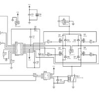
 

hip4082 application

No idea?
There were people who recommend HIP4082 for motor control in this forum.

If you couldn't find any answer to my first question, maybe you can answer this:

Which logic signals should i apply to the inputs of a HIP4082 in order to control a dc motor?

I'll be pleased for any response.
 

pwm hip4082

Here it is:


The bootstrap diodes aren't the best ones i can use i know but they were the fastest ones we have in our hand. I'll change them with UF400X diodes.

I didn't put the schematic of the logic circuit, since i wrote the signals that i apply to the IC in my first message.
 

hip4082 circuit

so could you highlight the correspondence between scope signal in doc you attached to mosfet gates in schematics above?
 

hip4082 dc motor

Artem, i put a modified file so that you can see them more easily. I labeled the signals with the same labels on the schematic.

And for the first message i wrote, just change the 'T's with 'Q's and everything will be ok.
 

hip4082 circuits

Can you check by scope the bootstrap voltage on capacitors C1 and C2?
If voltage does on C2 fall when Q2 is to open, you should check either D2 , Q2 and IC1 . One of them could be failed.
 

how to calculate bootstrap capacitor for hip4082

I changed every component many times with new ones. So it shouldn't be a problem related to a faulty component but i'll do what you said.

Other than that, i tried to connect a 1V power supply across C2 in order to eliminate the probability for that capacitor to charge to Vdd. The result was same. Can the bootstrap diodes lead to a problem like this? In Intersil's web page it recommends using bootstrap diodes which have a rating of trr < 50ns. The ones that i used have trr = 300ns.

I'll try to get a picture of the waveform across each bootstrap capacitor from the scope after trying with faster diodes.

Thanks for the response.
 

logic circuit

You say that voltage on bootstrap does fall and it is visible from picture.

But voltage on Q2 must be higher than voltage on Q3 - did you swapped gates of Q2 and Q3 when connected to IC ? i assumed that you just shift scope channel position for that .

Higher trr needs for higher switching frequency , but yours is 15 kHz and should not a problem , and there is no such problem for Q1.

How did you measure by scope ? What was the ground for scope ? Did you use load?
 

12 dc driver motor circuit+hip4082

The ground of the scope was connected to the circuit ground and the motor was connected as the load when i took the measurements. The amplitudes of the gate signals were normal. I just shifted the scope channel positions on the y axis and changed the volts/div settings for the second channel (the channel which i connect to upper gates) to make it possible to see both signals at the same time on the screen. Waveforms are the only things you should look in these images. Ignore the relative positions of the signals on the y axis..

In other words, the amplitude of the gate signal of Q2 ( > 60V since the supply voltage for the motor is 60V) was much higher than the amplitude of the voltage at the gate of Q3 (12V) , as it should.

The pictures i've attached show just the gate voltages of the MOSFETs since i haven't taken any picture of bootstrap voltages yet.

To prevent any confusion, i put a picture to show what i'm trying to achieve.

https://obrazki.elektroda.pl/19_1183546569.jpg
 

motor control - spike filtering

Yet also check waveforms on driver input for Q2.
 

hip4082 h bridge

It's low. There isn't any problem on the input signals. The weird thing is that, when i remove the motor, all of the mosfets start to operate as i expected.

One more question: (doesn't related to the problem)

What will happen if i turn Q3 off? I guess Q1 would never conduct since the bootstrap capacitor wouldn't charge to Vdd. Or would the capacitor charge through to motor?
 

dc motors hip4082

The bootstrap should be charged when Q4 is ON as :
Q4 C2 D2 Vdd. When There is signal to open Q2 , voltage on Q2 source will increase and D2 will be back biased.
 

hip4082+circuit diagram+dc motor control

I should somehow prevent the capacitor C2 from charging, since i don't want Q2 to conduct.
The same thing applies to C1, if i change the direction of rotation of the motor.

Can you tell me, which logic signals should i apply to HIP4082 for a behaviour like in the picture below?

https://obrazki.elektroda.pl/19_1183546569.jpg

The ones that i apply are here:

ALI -> PWM;
AHI -> logic low;
BLI -> Inverse PWM;
BHI -> PWM;

I guess the problem is about these logic signals. I don't understand exactly how the bootsrap capacitors work in this circuit and probably use wrong logic.
 

hip 4082+circuit diagram

i guess you should change switching sequence as:
- change the direction by upper mosfets (one is ON and another is OFF and vice versa for opposite direction )
- supply differential pwm signal to lower mosfets as it is shown in intersil datasheet page 3.

ALI -> PWM;
AHI -> logic low;
BLI -> Inverse PWM;
BHI -> logic high;

or for opposite direction

ALI -> inverse PWM;
AHI -> logic high;
BLI -> PWM;
BHI -> logic low;


Driver has internal shoot through prevention logic so you should not have a problem .

Int this case as above either current will be supplied through bridge diagonal or lower mosfet will be ON (to supply bootstrap capacitor charge).

Added after 15 minutes:

If you still have a problem , i assume you have differential waveform capability - measure the voltage on bootstrap capacitor as difference of drain to ground and capacitor to ground voltage. Is it decreasing while in operation ?

Also try to decrease motor voltage to check whether effect is disappeared.

what is the motor current ?

Can you also check for spikes on J3 connector motor power supply ? What are their amplitude ?
 

    s_cihan_tek

    Points: 2
    Helpful Answer Positive Rating
hip4082 capacitor

artem said:
i guess you should change switching sequence as:
- change the direction by upper mosfets (one is ON and another is OFF and vice versa for opposite direction )
- supply differential pwm signal to lower mosfets as it is shown in intersil datasheet page 3.

ALI -> PWM;
AHI -> logic low;
BLI -> Inverse PWM;
BHI -> logic high;

So you say that i should apply a "logic high" to BHI instead of a PWM. But according to the datasheet they're same because the IC will invert the lower gate signal to prevent shoot-through and apply that inverted signal ( in this case the inverse of the inverted PWM => PWM) to the higher MOSFET.

I'll take the measurements you said when i go to the lab again and hopefully find something that can give a clue about the problem.

Thank you very much for your interest.
 

break with hip4082

I did not read your problem from initial very well. As far as i understand now you have problem with high side A being goes into conducted state while it should not . Is it true ?
It could also be that due to long recovery time of bridge diodes , due to spike at side A goes high voltage on AHS exceeds max limit for hip4082 (80 V) and it might be nondestructive recoverable (may be avalanche ) failure happened for A side high drive output resulted in high signal at AHO . This can be checked by reducing motor voltage till spike level wont be high enough to break the chip.
If this is the case as a workaround can try to decrease rise time by increasing gate resistors 15R to something more , but mosfets will be heated more and you can try to use diodes with faster recovery time . I could be wrong in my previous remark regarding diode selection.

This can also be checked by running non inductive load instead of motor (high power resistor with same current rating as motor).


P.S. I am interesting in this problem as i am learning with you), and i like learning by problem example.
Regarding bootstrap internals check the www.irf.com an-978 HV floating mos gate driver ICs application note.
 

hip4082 h-bridge scematic

artem said:
As far as i understand now you have problem with high side A being goes into conducted state while it should not . Is it true ?

Yes, exactly.

artem said:
It could also be that due to long recovery time of bridge diodes , due to spike at side A goes high voltage on AHS exceeds max limit for hip4082 (80 V) and it might be nondestructive recoverable (may be avalanche ) failure happened for A side high drive output resulted in high signal at AHO . This can be checked by reducing motor voltage till spike level wont be high enough to break the chip.

I tried with UF400X diodes as well but the results were same. I'll look for spikes in the bootsrap capacitor voltage.

artem said:
This can also be checked by running non inductive load instead of motor (high power resistor with same current rating as motor).

Good point. I'll try that too.


We captured the waveform across the bootstrap capacitor. I'll put them here when they send them to me (I won't be in the lab for a few days). They say that there are spikes in the bootstrap capacitor voltage.
 

hip4082 h-bridge

Did you try to decrease motor voltage to check whether problem does get eliminated ?

Then regarding freewheel diodes on bridge - do they efficiently restrict motor spikes ?
DO you have spikes on C5 (first schematics )? Is it of good quality to reject spikes ?
If there are spikes on C5 could you try to put TVS on motor supply with limiting voltage less than 80 V ? Can you also try to use snubber parallel to motor to reduce spikes? (see ST microelectronics app note how to calculate snubber values an-280)
 

application hip4082

I attached a word document which contains pictures of the measurements we've recently done.
We connected a power resistor instead of a motor as a load and the circuit worked fine. The problem is related to the motor.

artem said:
Did you try to decrease motor voltage to check whether problem does get eliminated ?

Yes, we tried it and the problem still exists.


artem said:
Do you have spikes on C5 (first schematics )? Is it of good quality to reject spikes ?

Yes, we have, as you can see from the attached word document.
 

Status
Not open for further replies.

Similar threads

Part and Inventory Search

Welcome to EDABoard.com

Sponsor

Back
Top