Continue to Site

Welcome to EDAboard.com

Welcome to our site! EDAboard.com is an international Electronics Discussion Forum focused on EDA software, circuits, schematics, books, theory, papers, asic, pld, 8051, DSP, Network, RF, Analog Design, PCB, Service Manuals... and a whole lot more! To participate you need to register. Registration is free. Click here to register now.

DC/DC converter-battery charging-by solar panel

Status
Not open for further replies.

assu

Junior Member level 3
Joined
Dec 8, 2011
Messages
28
Helped
0
Reputation
0
Reaction score
0
Trophy points
1,281
Location
PAKISTAN
Visit site
Activity points
1,508
Greetings,
I have solar panel which produces following
Vmp=16V
Imp=7.5A
P=120W

Battery to be charged is 12V 45Ah Lead Acid
Now, I will be charging the battery at 14V and 5Amp (i.e., approx 10% of 45Amp)
I have found buck converter would be feasible for this solution but on the other hand if
PV Panel reduces its voltage to 12V due to less sunlight so i will have to boost the voltage while bargaining current less than 5amp

So should i design buck/boost OR Cuk converter for it. As many sources say Cuk is most reliable.
 

With a 120W panel, there is a chance that you'll be able to boost output from a darkened panel which is reduced to putting out 12V, such that you can obtain a charging voltage.

It may pay you to experiment with a buck-boost converter, since you can adjust duty cycle to suit all combinations of PV panel output, versus battery voltage.

The Cuk converter may work as well. The link below has helpful info.

boostbuck.com
thebuck/boost ckt i made
https://commons.wikimedia.org/wiki/...vg#mediaviewer/File:Buckboost_conventions.svg
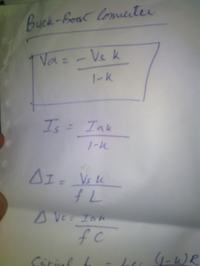
Well,experimenting is the only solution to get the best design working. However, what i have read over the internet and in some books CUK is best when u need continuous current and for the above stated project battery will be needing current. I have tried to calculate the inductance and Cap value for buck/boost using following equations:


You see if i want to get del I so i have assumed L=220uH value to be readily available in the local stores which gave me del I to be 1.04 Amp
similarly del V is calculated and C=2000uF gave me del Vc to be71.3mV
But in real the ckt doesnt produce the required voltage at a duty cycle(k) of 43% to be exact.

Now i am lil confused in the calculations. Well, the equations are taken from power electronics book Muhammad H. Rashid
 

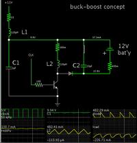
Here is a simulation showing how a buck-boost will work.

It illustrates how you can deliver a charge a 12V battery from a PV panel putting out just 11V at 130 mA.

By putting a choke on the supply feed, and an input smoothing capacitor, you can draw continuous current from the PV panel.

Most of the resistors are 'invisible', inserted to portray some amount of resistance in components.

A 220 uH coil can be operated at a frequency of tens of kHz. If you wish to convey 7.5 A from your PV panel, then your coil must be able to carry more than that amount of current.


An output capacitor is not needed when you are charging a battery.

A switched-coil converter should not be operated without a load. You may get high voltage spikes if you do. Furthermore an output capacitor will charge to an unpredictably high voltage.

By choke means this
https://en.wikipedia.org/wiki/Choke_(electronics)
Also is their any formula for calculating input cap ?

And shall the diode not be placed in opposite direction?


Sort of, but typically a filter is placed downstream of the pulsed waveform.
This is a filter that is positioned >upstream< of the circuit that creates the pulses.

Also is their any formula for calculating input cap ?

It's a case for experimentation. The coil-cap input filter may not even be needed when the PV panel is putting out 16V.

A PV panel is a peculiar kind of power supply. Depending on what load you hook up to it, it will provide a high voltage at tiny current, or a lot of current at low voltage. The simulator does not contain an accurate model of a PV panel.

And shall the diode not be placed in opposite direction?

This link will show you how the buck-boost works. It inverts the polarity of the power supply. Notice the battery icon is upside-down.

The link below will:
(a) open the site:
www.falstad.com/circuit
(b) load my schematic above, and
(c) run it on your computer (Click allow to permit the Java applet to load. You need to have Java installed on your computer.)

https://tinyurl.com/qbmgl55

You'll need to play with the values. Right-click on a component, and select Edit.
 
  • Like
Reactions: assu

    assu

    Points: 2
    Helpful Answer Positive Rating
Sort of, but typically a filter is placed downstream of the pulsed waveform.
This is a filter that is positioned >upstream< of the circuit that creates the pulses.


It's a case for experimentation. The coil-cap input filter may not even be needed when the PV panel is putting out 16V.

You'll need to play with the values. Right-click on a component, and select Edit.

well i tested the ckt physically and tend to get 7v at output without output cap but it couldnt drive any load may it be a 6v motor, no current was passing....
my source was a dc supply of 12v 1.2amp....
also whenever output cap was inserted the voltage drop to 1v....can u tell what could be the prob?

Diode used BY206,TRANSISTOR USED BC547
 
Last edited:

A likely problem is parasitic resistance. This might be in the power supply, switching device (transistor/mosfet). Possibly the coil.

High resistance will prevent adequate current flow.

You must make sure the switching device turns fully on and fully off. Its bias must be sufficiently high, and sufficiently low.
 

Parasitic resistance is a tough thing to find out, but then it leads me to try different types of inductor maybe iron core,for now i was using ferrit core....
Also it leads to try using MOSFET rather than npn transistor with base connected to 200Ohm resistance fed by PWM from MicroController
 

Please have a look at the below ckt and kindly tell what seems to be wrong... i cannot achieve 13.5VOLTS required to charge battery.

The mosfets are not turning on fully. Falstad's simulator seems to model mosfets so they turn on only at higher voltages. (As a result I often substitute transistors in simulations.)

While you are in this experimental stage, it will help if you start with everything simple.
Example, use analog switches. Drive them directly from a clock signal.
Example, use a diode in place of one of the switching devices.

Also make sure your converter stage is correctly drawn. Right now it does not match either a buck, or boost, or buck-boost.
 

Status
Not open for further replies.

Similar threads

Part and Inventory Search

Welcome to EDABoard.com

Sponsor

Back
Top