mycw
Junior Member level 3
Hello everyone,
I was looking on a product datasheet and found something confusing me: on CML output, with 50-ohm pull-up resistors, "the input impedance of the following stage should be high", but why?
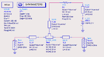
In my understanding, when we are simply considering RF signals, the equivalent input impedance seen by the transmission line will be a 50-ohm pull-up resistor in parallel with this high impedance next stage, which will be approximately 50-ohm again, but is it correct? Because apparently the results from ADS contradicts this hypothesis or maybe something is wrong configured in ADS? I used one 50-ohm terminal on the input side, and a large impedance terminal with 50-ohm pull-up resistor on the output side.
I really appreciate any comments. Thank you!
Mario Young
I was looking on a product datasheet and found something confusing me: on CML output, with 50-ohm pull-up resistors, "the input impedance of the following stage should be high", but why?
In my understanding, when we are simply considering RF signals, the equivalent input impedance seen by the transmission line will be a 50-ohm pull-up resistor in parallel with this high impedance next stage, which will be approximately 50-ohm again, but is it correct? Because apparently the results from ADS contradicts this hypothesis or maybe something is wrong configured in ADS? I used one 50-ohm terminal on the input side, and a large impedance terminal with 50-ohm pull-up resistor on the output side.
I really appreciate any comments. Thank you!
Mario Young
Last edited: