Continue to Site
Follow along with the video below to see how to install our site as a web app on your home screen.
Note: This feature may not be available in some browsers.
")
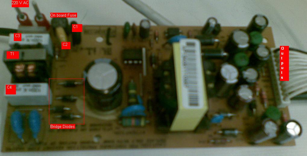
siavashhn said:the signal is not rectified, because I could see minus signals too.