Continue to Site

Welcome to EDAboard.com

Welcome to our site! EDAboard.com is an international Electronics Discussion Forum focused on EDA software, circuits, schematics, books, theory, papers, asic, pld, 8051, DSP, Network, RF, Analog Design, PCB, Service Manuals... and a whole lot more! To participate you need to register. Registration is free. Click here to register now.

Custom Segment LCD - Segments won't turn on - Please Help

Status
Not open for further replies.

vitess21

Newbie level 4
Joined
Jul 24, 2020
Messages
6
Helped
0
Reputation
0
Reaction score
0
Trophy points
1
Activity points
36
Hi
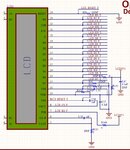
Using an existing LCD sample as reference, I have sourced out for competitor design of a similar LCD from another supplier to save on cost. When the competitor samples finally arrived, the LCD would not turn on. All voltages match however I notice a difference in segment mapping. Please see attachment.

My question is, if the pin mapping is off by one segment would that be enough for the LCD to not turn on? I would still expect to something on the LCD. Please help. Thank you.

LCD Specs

Driver: ST7036
Interface:6800 Series

LCD MAPPING.jpg
 

please show the schematic

i would expect the wrong symbols to appear if the issue was only a pin mapping error
the difference between common cathode and common anode would be enough for nothing to light up

likewise power and ground on the wrong pins, incorrect or insufficient power

also, if the display is multiplexed, nothing will light up if the ON part of the duty cycle is too short for the eye to see the light
and if the refresh rate is insufficient, the display could blink, or look like it never lights up
 
Thank you greatly for your prompt response!

What do you mean by " difference between common cathode and common anode"? How do I investigate this?
 

as an example, look at the data sheet for this 7 segment display

toward the bottom of the first page , it shows the schematics for common anode on left and common cathode on right
note all of the segments and the decimal point are diodes.

and this:
 

wwwfeldman

Thanks and well noted regarding common anode/cathod. Please see attached schematic as you requested. I appreciate your help, i have personally invested with the supplier so i can't afford a loss in NRE.
 

Attachments

  • LCD.jpg
    LCD.jpg
    184 KB · Views: 185

These are muxed LCD, no anode or cathode involved.

Post#5 changes the view, post #1 looks like you are driving the LCD glass with some circuit, post #5 suggests that you have an LCD display with controller and the diagram in post #1 is only documenting the internal organisation. In this case, you need to configure the LCD display according to the datasheet, there may be any kind of differences between both devices, even if they use the same controller chip.
 

My question is, if the pin mapping is off by one segment would that be enough for the LCD to not turn on?

It is unlikely to have the byte shift indicated in post #1, most likely it is a question of nomeclature, in which the manufacturer of one probably referred to the nth byte, whereas the other may have referred to the offset, which could explain the 1-byte shift between both documentation.
 

as andre suggests, the byte shift may be due to the difference between starting at 0 or 1 .

what are all the connection the pins wired to?
please show the rest of the schematic(s?)

there is something missing, at least in my understanding:
for example:
pin 19 (D0) goes to LCD D0 T and LCD D3 F
pin 16 (D3) goes to LCD D0 F and LCD D3 T
this repeats for most of the pins

it appears to be wired for two different configurations of LCD
either use the T connections or the F connection -
i assume T and F indicate the specific LCD that is installed

Your assumption is correct! The PCB has provisioning for 3rd LCD supplier which has different pin configuration, allowed by 0 Ohm jumpers. And yes the LCD has driver ST7036 embedded and is controlled by STM microcontroller. For this set up, i am only using pins with 'T' suffix
 

It is unlikely to have the byte shift indicated in post #1, most likely it is a question of nomeclature, in which the manufacturer of one probably referred to the nth byte, whereas the other may have referred to the offset, which could explain the 1-byte shift between both documentation.
Thanks for response. But do you think a offset reference would cause the entire LCD not to display? I would expect wrong segment sequence but it should still be displayed something.
 

Your assumption is correct! The PCB has provisioning for 3rd LCD supplier which has different pin configuration, allowed by 0 Ohm jumpers. And yes the LCD has driver ST7036 embedded and is controlled by STM microcontroller. For this set up, i am only using pins with 'T' suffix

do you have the jumpers in the right places?
did you try changing the jumpers?

are power and ground wired to the correct places and voltages for the LCD in use?

please provide the data sheets for the LCD sample used as a reference
and for the similar LCD from a different supplier?
 

Hi,

Possible reasons fo a display glass not to work:

1) Display glasses are manufactured for a dedicated driving voltage.
So if the new one is designed for a higher voltage than applied, then it's possible to see no activated segments.

2) shifting the SEGment connections will just cause different segments to be activated, but they should be visible.
But shifting the COM connections may cause the segments not to be activated. Check proper COM connections to your display controller.

3) LCD glasses work by shifting the light's polarity angle, thus they need a polarizing filter. If this polarizing filter is missing you will se no activated segment.
I don't know how those filters are specified, but I assume for a test you could use one designed for a photo camera. Ask a photographer to get one for tests.
Test: use the filter and place it over your unconnected display. Rotate the filter with respect to the display glass. Look through the filter to the display glass. If the display does not change color (it should become 2x dark and 2x clear during one complete revolution), then there is no filter applied on the display.
* In this case connect the display, use any test pattern, place the filter on top of the display. Rotate the filter while you check for activated segments.
* If you see clear and dark while rotating, then a polarizing filter is already applied on the display. No need for an extra filter (photographer) for further tests.

*********

You may do some tests with DC by hand. Note: Permanent DC may cause damage to the display, but for a few seconds it should be no problem. Applying 5V, one at a SEG, the other to any COM, should activate a segment. Polarity does not matter.

Good luck.

Klaus
Thank you greatly for your advise. I will certainly try this and get back to you.
 

Status
Not open for further replies.

Similar threads

Part and Inventory Search

Welcome to EDABoard.com

Sponsor

Back
Top