Continue to Site

Welcome to EDAboard.com

Welcome to our site! EDAboard.com is an international Electronics Discussion Forum focused on EDA software, circuits, schematics, books, theory, papers, asic, pld, 8051, DSP, Network, RF, Analog Design, PCB, Service Manuals... and a whole lot more! To participate you need to register. Registration is free. Click here to register now.

[SOLVED] Curved microstrip with S21 above 0dB (Momentum)

Status
Not open for further replies.

mycw

Junior Member level 3
Joined
Sep 29, 2010
Messages
30
Helped
2
Reputation
4
Reaction score
1
Trophy points
1,288
Activity points
1,500
Hello everyone,

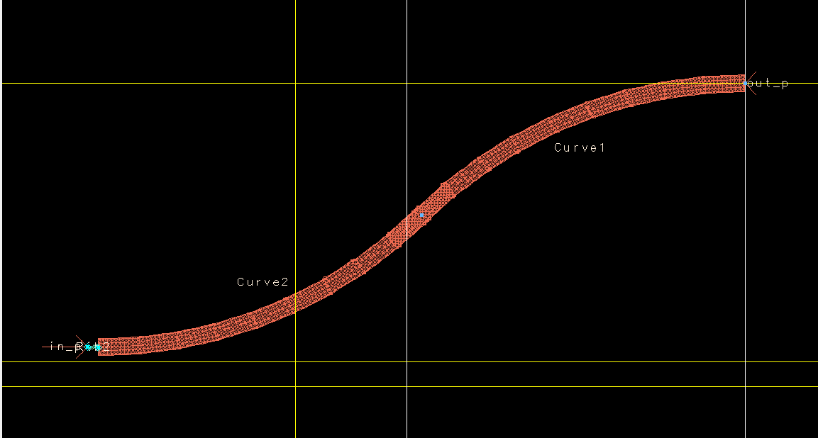
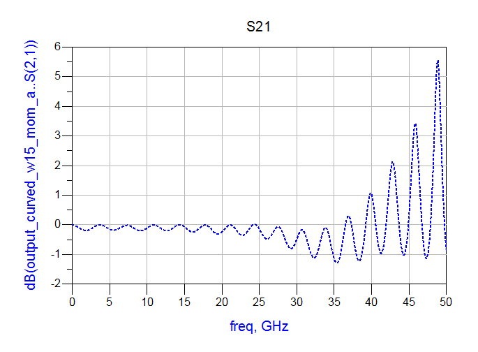
I'm designing a curved microstrip for broadband TIA (40GHz+), but I found from momentum the S21 could reach above 0dB with my microstrip line only (gain on pure passive circuit?!). I checked the substrate setting, RF mode is off, is there anything else that I can verify? The layout and S21 are attached. THANKS A LOT!!!!


Mario Young
 

HI
how many port do you have in your design ?
have u ever listened " ISOLATION " ?
ok. I think u should reseach "ISOLATION". it's very meaningful. if you have difficult about reseach "isolation", PM FOR ME. I'll talk for you. ok
 
  • Like
Reactions: mycw

    mycw

    Points: 2
    Helpful Answer Positive Rating
Hi vcoltech,

Thanks for your suggestion, I didn't pay attention about isolation, will try to find out more about it.

In this simulation file, there are only two ports, one in and one out. But the actual circuit it will be a differential pair, I was running on single-ended line because I was trying to find the shape with lowest loss.


Mario Young
 

What is the yellow line? Is it a waveguide or box?
 

Hi tony_lth,

The yellow lines are construction lines for positioning, and it is only microstrip lines.
 

I would have a look at port calibration.

Not sure about Momentum, but in Sonnet non-passive data usually means that something is
wrong with the port calibration (no proper ground return, overmoded substrate etc.)

What is your substrate?
Where is your ground return for the current?
 

Thanks everyone, I solved the problem by adding its counterpart, actually it is a differential pair, I thought I can simulate them separately. About P1 touching the line, in fact there is a bonding wire between P1 and the starting point of the transmission line, sorry it is not clear on the graph attached. Thanks again!
 

Status
Not open for further replies.

Part and Inventory Search

Welcome to EDABoard.com

Sponsor

Back
Top