T
treez
Guest
Hello,
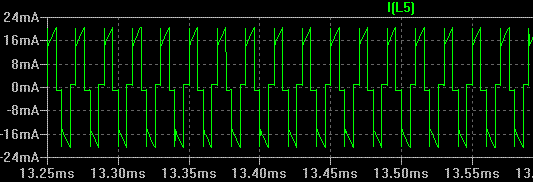
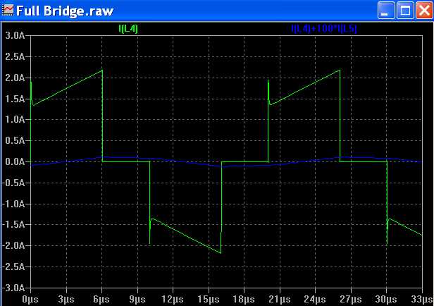
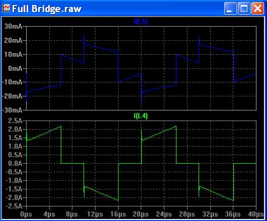
In the attached LTspice sim of a full bridge smps, we see that magnetising current in the secondary of the current transformer has a negative slope.
This seems counter intuitive.
But is the wisdom involved in its analysis, concerning the fact that the field due to the secondary is the opposite of that due to the primary coil, and so the magnetising current is reducing as the current pulse goes forth?