juz_ad
Full Member level 2
Hello - this is my first post here.
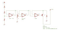
I need to design a suitable voltage-controlled current source to drive a 4x transistor differential amp (long-tail pair) - like this:
Wikipedia: Long-tailed-pair
I've never used a transistor diff-amp before so this is just for testing and proof-of-concept - I am trying to learn about discrete OTAs.
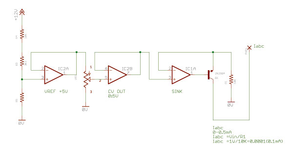
I started with this:
It takes a control voltage of 0 to 5V, and sinks approx. 0 to 0.5mA at Iabc. My decision to use 0.5mA is based on the input current for the CA3080 OTA.
My understanding is that the current input for the differential amp needs to be referenced to -V so I don't think my design will work as it is?
Can anyone suggest changes I can make to my design or a new design to look at or any advice to get me started.
Thanks.
I need to design a suitable voltage-controlled current source to drive a 4x transistor differential amp (long-tail pair) - like this:
Wikipedia: Long-tailed-pair
I've never used a transistor diff-amp before so this is just for testing and proof-of-concept - I am trying to learn about discrete OTAs.
I started with this:
It takes a control voltage of 0 to 5V, and sinks approx. 0 to 0.5mA at Iabc. My decision to use 0.5mA is based on the input current for the CA3080 OTA.
My understanding is that the current input for the differential amp needs to be referenced to -V so I don't think my design will work as it is?
Can anyone suggest changes I can make to my design or a new design to look at or any advice to get me started.
Thanks.