Continue to Site

Welcome to EDAboard.com

Welcome to our site! EDAboard.com is an international Electronics Discussion Forum focused on EDA software, circuits, schematics, books, theory, papers, asic, pld, 8051, DSP, Network, RF, Analog Design, PCB, Service Manuals... and a whole lot more! To participate you need to register. Registration is free. Click here to register now.

current sensor in smart energy meter

Status
Not open for further replies.

sunny_s

Newbie level 5
Joined
Apr 5, 2011
Messages
9
Helped
0
Reputation
0
Reaction score
0
Trophy points
1,281
Activity points
1,344
hi friends...! i am new to the form...
i am doing a project named smart energy meter using ic's ade7757 and 89c51...this project aims to calculate power consumed by load....the ade7757 ic does the calculations and gives digital output in the form of frequency whose number of pulses are to be calculated by 89c51...But the problem i got is the "350 micro ohm" shunt resistance, which is used for current sensing...! the voltage drop across shunt is given to current channel of ade7757...! i am unable to find shunt in retail shops of my city. could u guys please help me in this regard....or any alternative for shunt resistance....thanks in advance for the help...!
 

Basically, a piece of resistance wire (Nichrome or constantan) will do as well. You're not restricted to a particular resistance value and can also use other current sense options, check the ADE77xx data sheet.
 
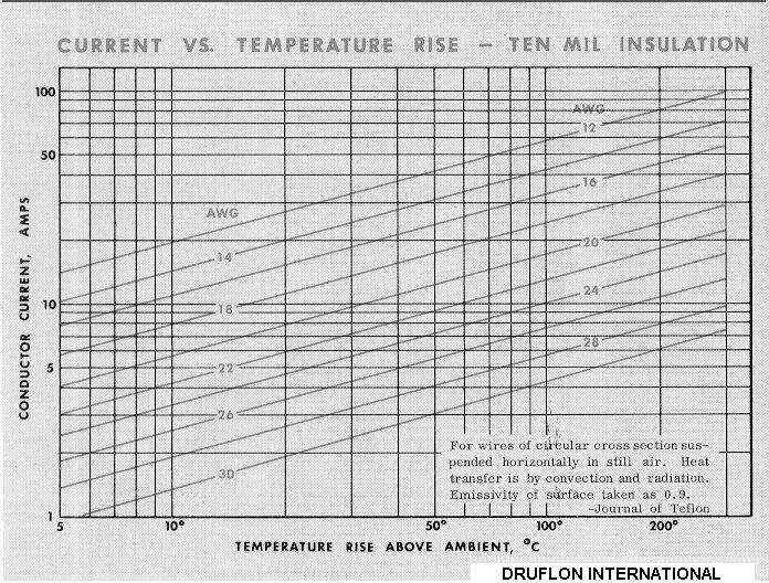
Take a look on table bellow.
You can build that resistance with winding wire.
Make a choice in wich turns amount don´t generate too high indutance ( thus avoiding induce to circuits around ).

With AWG-20 - for example - you can match ~350 uOHM with 1cm.

**broken link removed**
 
thank you guys...! this is really useful,by using (Nichrome or constantan) or a copper wire of appropriate awg, hope i can get shunt value....now i'l get into trying this & post the result....thank u guys 1nce again....!
 

sunny

I forgot to say that current flowing at the wire have a limitation.
Generally is used rise temperature constraint.

To above AWG-20 example yelds to +10oC currente of around 5A.

cndgrph2.jpg
 
don't forget that the resistance of copper wire chages 30% from 20 degC to 100 deg C and for this reason is not used much in shunts, for accuracies of 1% or better you need manganin... Regards Orson Cart.
 
Is the meter intended to monitor household appliances? Then the shunt must carry the full current going to the appliance.

It must be a large enough gauge so it won't heat up. And it should have just enough resistance to generate a measurable voltage drop.

Say you're measuring appliances drawing up to 15 amps. Consulting an electrician's handbook we find the safe stuff to carry that amount is 12 gauge copper wire. Meaning nichrome wires won't do the job.

A ten inch length of 12 ga is suitable to start with. That will generate sufficient AC voltage drop to measure.

Tailor your op amp circuit to multiply the voltage proportionately. (For AC amplification.)

The project description should tell how to calibrate the circuit.
 
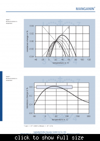
the load i am using draws at max 5 amp current...and i observed the thermal stability of manganin is more...so thinking to go with manganin wire....see the characteristics in this image
 

I'm somewhat surprized, that several contributors seriously suggested copper wire. But you have realized, why it isn't a reasonable option. For technical metering applications, 0.5 or 1% error over the specified temperature range won't be bad. I guess, you'll have difficulties to provide a better calibration for the instrument. But there's nothing against achieving a lower T.C. for the shunt of course. You also have to care for a suitable 4-terminal shunt circuit, not to lose accuracy due to unintended voltage drops.
 
hi FvM,


I have to agree to you and would say sorry to the members.
In fact, I already used that solution in protection sense enviroment to equipment where main requirement where imperative to be low cost. ( ilumination lamp driver ).

Actually, that application is different from the measurement asked here, wich requires a precision behaviour too high.

+++
 
I once made a similar project for the purpose of counting amp-hours coming from a solar panel.

It never occurred to me that the current-sensing shunt wire had to be made from exotic metals. To tell the truth I didn't realize copper's resistance can change by several percent.

So maybe copper isn't the ideal shunt material. Yet what are the wires powering the appliance made of? Copper. Don't they drop a volt or two as high current heats them up making their resistance go up?

In any case I simply used several inches of 10 ga copper wire. Max current 20 amps. Looked at a table and saw 10 ga recommended. Didn't expect the shunt to heat up.

I used an op amp to sense voltage drop at its ends.

My project had several sections. Adjusting each one properly required substantial time and effort.

Example... one hurdle was when I discovered output did not read 0 volts when no current was flowing. In other words I had to solve an offset error in the op amp circuit. The solution involved soldering in a carefully measured and tested resistor network.

I needed a pulse generator (vco) which performed to an acceptable standard of linearity over a range of 1:1000. This involved time and effort testing several different designs (which didn't suit). Finally I managed to develop a vco which showed a straight line when I graphed pulse frequency coming out versus analog voltage going in.

Later on I had to adjust the pulse frequency to calibrate to the digital readout. More time and effort. You'll likewise want to test the accuracy of your meter (however your ingenuity finds to do this).

What I'm saying is that this project will provide plenty of hurdles. Any one of them can impact the accuracy of your meter to a greater extent than the temperature stability of the shunt.

Many gremlins to be conquered.


It's proper that you strive for accuracy in the first stage of the measuring process. But there's also the job of securing the shunt so it never flexes or comes loose. Because if it disconnects, you'll have high voltage and/or high current inflicting mayhem on the other circuits. You must maintain intimate electrical contact between the shunt and adjacent load-carrying wires. Again, looseness or disconnect can send heavy current through the project's delicate circuits.

I managed to make a usable amp-hour meter. No doubt you'll succeed with your meter.
 
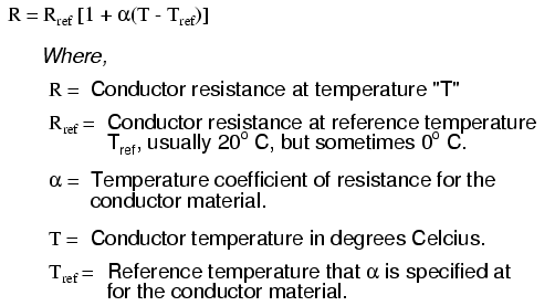
If we consider a copper wire working in an operating range from -10oC to +40oC it results in a drift of :
Delta(R/Rref) = 0.004041 * (50) = ~20%

So, this solution cannot be applied in a smart metter like that, but there are a wide others where no much precision are required.

+++

Material Element/Alloy "alpha" per degree Celsius
==========================================================
Nickel -------- Element --------------- 0.005866
Iron ---------- Element --------------- 0.005671
Molybdenum ---- Element --------------- 0.004579
Tungsten ------ Element --------------- 0.004403
Aluminum ------ Element --------------- 0.004308
Copper -------- Element --------------- 0.004041
Silver -------- Element --------------- 0.003819
Platinum ------ Element --------------- 0.003729
Gold ---------- Element --------------- 0.003715
Zinc ---------- Element --------------- 0.003847
Steel* --------- Alloy ---------------- 0.003
Nichrome ------- Alloy ---------------- 0.00017
Nichrome V ----- Alloy ---------------- 0.00013
Manganin ------- Alloy ------------ +/- 0.000015
Constantan ----- Alloy --------------- -0.000074


10226.png
 
hi,

BradtheRad....really there are much other factors to be considered, as you said in your experiences and thanks for being optimistic about my project:smile:

and as andre_teprom mentioned the coefficients, its good to opt for other metal for better accuracy....i'l soon post the result....
 

Status
Not open for further replies.

Part and Inventory Search

Welcome to EDABoard.com

Sponsor

Back
Top