Continue to Site

Welcome to EDAboard.com

Welcome to our site! EDAboard.com is an international Electronics Discussion Forum focused on EDA software, circuits, schematics, books, theory, papers, asic, pld, 8051, DSP, Network, RF, Analog Design, PCB, Service Manuals... and a whole lot more! To participate you need to register. Registration is free. Click here to register now.

Current Sensing with the CT1248

Status
Not open for further replies.

Bjtpower

Full Member level 5
Joined
Dec 24, 2015
Messages
297
Helped
2
Reputation
4
Reaction score
2
Trophy points
1,298
Activity points
3,893
Dear Friends

i am planning to develop a isolated current Sensing Methods for AC Current sensing.

I have one CT1248 (1:1500) and recommended Burden is 84ohm

Now if i want to amplify the same signal and give it to the Controller Pin.

What will be the Probable circuit..??

I have used earlier AD620 for amplification but its not the good selections as it is Differential Amplifier and full voltage swings to 2.2V when we apply 3.3V supply at its terminals

i want to have full access of 3.3V which we can give it to the Controller.

current sense.PNG

Regards
Marx
 

Hi,

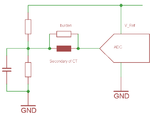
I usually recommend to just bias the CT secondary to ADC_range/2 then feed it to the ADC input.
It is the most flexible and simple (hardware) solution.

But without knowing about currents and frequencies and without knowing WHAT you want to measure (true RMS, fake RMS, rectified average....) and other parameters .... it's about impossible to give a recommendation.

Klaus
 

If the CT doesn't provide 3 Vpp swing with sufficient linearity, you'll need a rail-to-rail amplifier. I don't see a particularly advantage of instrumentation amplifier for this function. Transimpedance amplifier configuration achieves lowest CT linearity error.
 

Seconding the transimpedance amp suggestion. Just make sure the opamp will maintain low distortion while handling the full secondary current of the CT. But you will need additional circuitry to bias the output's common mode voltage.
 

Just make sure the opamp will maintain low distortion while handling the full secondary current of the CT.

Forgot to mention that it's only useful for CTs with low mA secondary current. CT1248 has 10 A rated primary current (9.5 mA secondary peak current, so it falls in this category). Regular burden and single ended voltage amplifier would work too, of course.
 

Forgot to mention that it's only useful for CTs with low mA secondary current. CT1248 has 10 A rated primary current (9.5 mA secondary peak current, so it falls in this category). Regular burden and single ended voltage amplifier would work too, of course.

How 9.5mA..??

My Calculations are here
Voltage drop across secondary Burden:1/1500=0.66mA (When passing 1 amp through primary)

Recommended Value for Burden resistor=94Ω
Voltage Drop across Burden resistor=94x0.66mA=62.4mV (Between IN+/IN- Pins)

check for attached
voltage drop.PNG
voltage drop1.PNG

- - - Updated - - -

Hi,

I usually recommend to just bias the CT secondary to ADC_range/2 then feed it to the ADC input.
It is the most flexible and simple (hardware) solution.

Klaus
Hi Klaus..

How we can Bias without op-amp..??

I never used the circuits like this..
 
Last edited:

But i want to connect it to the controller..

Are you elaborating that reference generated by the Voltage divider should mix with the ac voltage getting across the Diodes or 2 RESISTORS..??

pls post schematics if its easy to show you
 

Hi,

diodes???

ct_bias.png

Klaus
 
Last edited:

Status
Not open for further replies.

Similar threads

Part and Inventory Search

Welcome to EDABoard.com

Sponsor

Back
Top