Continue to Site

Welcome to EDAboard.com

Welcome to our site! EDAboard.com is an international Electronics Discussion Forum focused on EDA software, circuits, schematics, books, theory, papers, asic, pld, 8051, DSP, Network, RF, Analog Design, PCB, Service Manuals... and a whole lot more! To participate you need to register. Registration is free. Click here to register now.

Current sense transformer saturation at 100% duty cycle.

Status
Not open for further replies.

cupoftea

Advanced Member level 5
Joined
Jun 13, 2021
Messages
2,589
Helped
54
Reputation
108
Reaction score
115
Trophy points
63
Activity points
13,602
Hi,

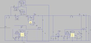
The attached 300W COT Buck has vin = 30 to 175Vdc

Its vout is to be 36vdc (whenever vin>vout).

When Vin < 36V, the Buck FET is required to be ON all the time. (100% duty cycle).

As such, the Constant Off time control sorts all this out nicely

The problem is that the Current sense transformer saturates whenever the Buck FET is ON with 100% duty cycle. (the red waveform attached shows this, it is the magnetising current in the secondary of the CST……well, AYK, it wouldn’t go that high in real life , but does in the LTspice sim, since AYK, LTspice doesn’t do saturation)

Anyway, the LTspice sim shows no problem when the vin rises back above 36V, the CST just resumes normal operation.

However, do you think we need to capacitively couple a switched voltage (at ~100khz) across the CST secondary, in order to force the secondary magnetising current to keep low (ie, below core saturation)?

AYK, all we need to do , is add circuitry to assure that Vsec_ON = Vsec_OFF

Buck COT with CST.jpg


Magnetising current in red (2ndary of CST).jpg
 

Attachments

  • buk_COT__normal.zip
    2.2 KB · Views: 81

Hi,

100% duty cycle means DC. Every passive CT goes into saturation.

Adding a capacitor at the scondary side can not avoid this, since the primary side causes the DC.
Instead adding the capacitor causes the voltage at the transformer to rise and thus it sooner gets into saturation.
You already know about "Vus" saturation criterium.

Klaus
 
If 100% on then why do you care about sensing current?
Thanks, when 100% ON, we only need to sense overcurrent, and then the FET should start switching......till the overload is removed.
 

Perhaps you want a "backstop" current sense for the
protection function, like a "desat detector" using FET
Ron? Or use the CT primary "winding" as a sense
resistor?
 
Thanks,
The attached is a constant off time Surge Buck converter which feeds a 300W Boost converter. The Surge Buck has two parallel CSTs ahead of it, which are switched alternately, therefore the buck fet can go to 100% duty and no problem.
Can you think of a lower component count way of achieving the 100% duty Buck?
When theres no surge the Buck should just go to “FET on all the time” (unless its overloaded, and then the buck should limit the overcurrent.
 

Attachments

  • 300w boost with surge buck.jpg
    300w boost with surge buck.jpg
    143.5 KB · Views: 99
  • 300W Boost with surge buck.zip
    4.3 KB · Views: 80

Thanks, but what about the following...

The attached is a 300W Buck converter, vin=10-36vdc, vout = 32v, pout = 300w.

Suffers occasional surges to 175vdc for 500ms.

The Surge Buck is needed to Buck down the 175Vdc surge, as shown. The Surge Buck lies dormant when there is no surge. As such, it is done in Constant Off Time Mode as shown. There is a current sense transformer for the Surge Buck, this obviously saturates when the Surge Buck is dormant, and then the shown comparator stands guard against any overcurrents. When the surge comes, the comparator staves off the initial overcurrent, then the CST comes out of saturation and does its job again.

The thing is that the Buck inductor rings with the input capacitor bank, and as such the system goes into oscillation, if vin is suddenly applied at min vin. So, When started up on min vin the input current bounces repeatedly off the current limit giving an unwanted oscillating system. As such, the shown current clamp has to be added to stop this.

It does the job, but it’s a large swathe of circuitry, and just makes you think, “there must be a better way”…can you think of it?

LTspice and jpeg attached
(oops, R38 and C19 need removing from the jpeg)
 

Attachments

  • 300W Full Bridge with 175vdc surge.jpg
    300W Full Bridge with 175vdc surge.jpg
    174.3 KB · Views: 94
  • 300W FullBridge with SurgeBuck______1.zip
    6.8 KB · Views: 74
Last edited:

If its OK, i will make another new thread related to this please?...since the surge buck front end is getting ridiculoulsy large, and woudl benefit from a new thread, please may i do this?
 

Status
Not open for further replies.

Similar threads

Part and Inventory Search

Welcome to EDABoard.com

Sponsor

Back
Top