Continue to Site

Welcome to EDAboard.com

Welcome to our site! EDAboard.com is an international Electronics Discussion Forum focused on EDA software, circuits, schematics, books, theory, papers, asic, pld, 8051, DSP, Network, RF, Analog Design, PCB, Service Manuals... and a whole lot more! To participate you need to register. Registration is free. Click here to register now.

current sense resistor modifications

Status
Not open for further replies.

sdowney717

Member level 1
Joined
Nov 2, 2012
Messages
35
Helped
1
Reputation
2
Reaction score
1
Trophy points
1,288
Activity points
1,689
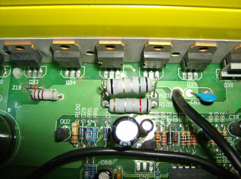
I was trying to determine the values for these 2 resistors using this calculator, but one seems to be invalid colors?
I think the upper is .58 ohms and the lower is .28 ohms.

What i want to do is I think lower the value of these two resistors by about 35% which will boost the inverter output by 35% from 1500 watts to 2000 watts which is still below the design capacity of the components. They made this very conservatively, it is fused for 240 amps at 12volts. 8 times 30 amp fuses is 240 amps total. And the mosfets are lots of them and all well rated beyond what this is set to shut down at.

So i was thinking to add two 0.1 ohm resistors in parallel with these both, which will lower the resistance which will lower the voltage drop across these resistors which will make the inverter circuitry think less amps are flowing which will boost the output capability to 2000 watts.

Will that work, or use another value?
HPIM1254.JPG
 

Hello sdowney717, I guess you forgot to include some schematic to illustrate the point you have trouble. Please provide more information to allow the people to help you.
 

I used this calculator for resistor determination https://www.dannyg.com/examples/res2/resistor.htm Its a 4 color band calc. With this the resistors are 0.05 and 0.02 ohms. I feel these are more closer approximation.

The current sense resistors are not expected to alter the circuit functioning in which they are installed. They are merely sitting their and sensing the amount of current flown and not put limit on it. So the change you are thinking is hardly going to affect the power output.
 

That's a pretty shaky theory about boosting the output. Even if it works like you're hoping, reducing those resistors by 35% would give you 1/.65 or 1.54 the output you had. So a 54% increase. Most likely increasing voltage or current will lead to a linear increase of the other, which gives you an exponential increase in power.

1.54^2*1500 = 3557.4 = snap, crackle, pop

So take it easy.
 

I used this calculator for resistor determination https://www.dannyg.com/examples/res2/resistor.htm Its a 4 color band calc. With this the resistors are 0.05 and 0.02 ohms. I feel these are more closer approximation.

The current sense resistors are not expected to alter the circuit functioning in which they are installed. They are merely sitting their and sensing the amount of current flown and not put limit on it. So the change you are thinking is hardly going to affect the power output.

I also created this thread here with the same question.
https://forum.allaboutcircuits.com/threads/current-sense-resistor-value.109782/

That calculator you showed me is the first one to actually give working numbers.

I created a steel wire shunt 0.027 inch diameter (.63 mm) and 3.25 inches long, wired in parallel with the two resistors.
I also measured the milli volt drops for various loads with and without the shunt.
I can with the shunt run the large microwave load, the inverter does not shut down.

You can read my last post there to see what they read. It seems to be about a 30% drop in the millivolts reading for a variety of loads, so I think the inverter circuitry is now thinking 30% less current is flowing than really is, so the circuit wont shut it down. I can not draw enough current with a single old car battery to really know what it might be able to do now, but it does run that large microwave oven now.

It must have affected the overcurrent shutdown to a higher value.

Any more thoughts on this?

- - - Updated - - -

Just adding this modification is on a Go Power 1750 HD 12 vdc MSW inverter.
 

The other thread gave more information on what you did ...
Okay, now i understand what you want to do. But you put confusing theory to make mod to this inverter and run heavier loads.

With the mod of adding a shunt, you basically fooled the safety control loop in inverter to think that it is sensing lower current, always. There is no boost of power happening because of this. What has happened is, in sense circuit the mod has been to reduce the drop across the sense resistor but the limit of this sense voltage reduction is not transferred to the control circuit suitably. The reference for the control/ shut down block is still the same. So it always sees a "lower current" drawn by the load.
 

Yes exactly. Since it still is measuring a change in current, the inverter will I think shut off on a higher load, although I dont know what load that is now. Seeing the milivolt pattern between the oem and the added shunt seems fairly linear across the tested range of maybe 30%, I am guessing it will shutdown at a 30% higher load than before.

Doing this also affected the bar amp draw display on the panel, it shows less amps being drawn , but it was never very accurate, more of a toy bar graph. It did not affect the low voltage DC bar graph display.

The internal components seemed to me capable with some mods of being a more powerful inverter. Having a threshold of 1500 watts for this design to that was not able to perform to it's potential, is a waste to me. What started this was it shutting down trying to power a 1600 watt microwave load. And I wanted a backup inverter to another one.

I think the worst that would happen is the output fets would blow, I then would use higher amp rated output fets which I have some here.
Or the input fuses would blow. My old battery I t still could not draw more than 150 amps from, so maybe today will test on a battery bank which has upto 450 amps available.

The inverter fan spins at power on, then goes off. And it has yet to heat up enough to even turn on the cooling fan.
 
Last edited:

I think there is enough safety in the inverter design so it is still running cool @ 1600W. But be cautious of running higher loads when manf is not guaranteeing. Because the limit would not be set arbitrarily, there will be consideration of lot of parameters like component value tolerance, working environment, type of load, process variation etc.
 
Well, in a way it was fun. What I thought might happen did happen.
I destroyed the inverter's input mosfets.

I looked into what happened and the board traces are too weak to support the higher current on the DC side.
Two drain traces opened under load, then that overloaded couple more input mosfets and one input mosfet burned pretty hard, the whole time the inverter kept on running.
Odd that it did this while only running a floor vac at the boat? The boat has three big batteries with lots of available amps for an inverter to use.

So I am rebuilding the copper mosfet traces with a copper wire soldered in, it fit all the way along nicely, and for the other source traces I beefed them up with thick solder.
I also plan to use IRF1010E input mosfets which has an 85 amp rating, the ones they used were 50 amp rated.

Personally, I think inverters are a nice concept, but highly overrated! Glad I do have a generator.
 

It is working again. I used IRF 1010E instead of FQP50N06. The IRF 1010E have an 85 amp rating versus 50 amp rating.
Since I replaced all 16 of them, I suppose the various parameters, capacitances etc... dont matter so much.

Here are the mods I made to help the board survive.
Soldered on a bare copper wire along the source circuit, it actually did not burn those circuit traces there.


Added eight 12 gauge wires to the 12vdc buss. the wires fit under the board with plenty of room. I drilled some holes, but the black wire ends at the buss, the way the board is made, cant drill, so they are just soldered on top. The case is negative grounded. The buss bars are inadequate for the current, they got very warm under load before, now they stay cool.


top view, I reinforced and had to repair several traces for the Mosfet drains.
4 had burnt out their copper trace connection going to the transformers.

 
Last edited by a moderator:

Status
Not open for further replies.

Part and Inventory Search

Welcome to EDABoard.com

Sponsor

Back
Top