Continue to Site

Welcome to EDAboard.com

Welcome to our site! EDAboard.com is an international Electronics Discussion Forum focused on EDA software, circuits, schematics, books, theory, papers, asic, pld, 8051, DSP, Network, RF, Analog Design, PCB, Service Manuals... and a whole lot more! To participate you need to register. Registration is free. Click here to register now.

Current ringing in H bridge

Status
Not open for further replies.

mrinalmani

Advanced Member level 1
Joined
Oct 7, 2011
Messages
463
Helped
60
Reputation
121
Reaction score
58
Trophy points
1,318
Location
Delhi, India
Activity points
5,285
Hi
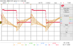
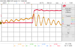
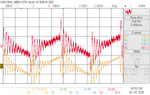
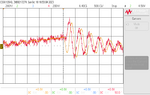
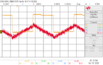
I have a tied an RL load to a 12V H-Bridge operating in a usual fashion where alternate FETs are ON followed by a large dead time where all FETs are OFF and then the adjacent pair of FETs are turned ON and the cycle repeats.
L = 32uH wound on gapped ferrite core.
R = 0.25 Ohm
To sense the current, I have probed directly across the resistor.
The problem is that the current is ringing very bad.
In the close up view of the waveform we can see that when the FETs turn off, the current shoots up in the same very direction in which it was flowing prior to turn off. I do not understand what is causing this ring. Parasitic capacitance of the inductor?
Please share your views.
In the image below, Pink = voltage and Yellow = current.
Thank you
 

Attachments

  • scope_49.png
    scope_49.png
    36.9 KB · Views: 258
  • scope_50.png
    scope_50.png
    30.3 KB · Views: 222

Last edited:

    mrinalmani

    Points: 2
    Helpful Answer Positive Rating
Inductor parallel capacitance may play a role, I rather suspect a flawed current measurement. Please show how you probe the shunt voltage.

In the end it can be a combination of both:

A certain (much smaller than indicated by the waveform) 2.5 MHz ringing and a massive overestimate of high frequency current components due to shunt inductance.
 
Last edited:

    mrinalmani

    Points: 2
    Helpful Answer Positive Rating
My first thought is that it's a result of poor probing of the circuit. You can see that the pink waveform also has the same ringing in it, though much harder to see because it's at 5V/div. Make sure your probes' grounds are put right at the GND of the H bridge. And make sure your H bridge has sufficient bypass capacitors placed right at the FETs.

A picture of the setup would help.
 

likely you have a lot of wiring between the mosfets and the nearest supply capacitor - insufficient de-coupling is a standard newbie issue.
 

when the FETs turn off, the current shoots up in the same very direction in which it was flowing prior to turn off.

This also occurs in my simulations. An inductor that is abruptly shut-off wants to continue to conduct. It generates current briefly as a spike (possibly a high-voltage spike). Or yanks current through neighboring circuitry depending on how you look at it.

Dead time makes this behavior more obvious. Moreover ringing suggests a capacitor is nearby.

Try installing back-to-back zener diodes (12V) across the inductor to act as a snubber. Or, try slower shut-off.
 

you need L & C for ringing - the C is the mosfet capacitances, the L is in the wiring to the bus caps ( if any ) and their ESL ....
 

Voltage waveform in post #1 has remarkable low ringing at both edges. It's about to impossible to get such a waveform in badly bypassed bridge. Nevertheless I would appreciate a photo or layout drawing of the circuit.
 
Hi thanks everyone for the reply.
After all the suggestions, I tried to see the effect of probing. In the protos of the previous post VDS was measured using a HV differential probe and inductor current using a normal passive probe.
I made three measurements:
1. Measure current with differential probe
2. Measure current with differential and passive probe hooked simultaneously across the shunt resistor.
3. Measure VDS with passive probe and current with differential probe. (Reverse case of the photos in the above post where passive was used for current and differential for voltage)

Case 1: Ringing disappeared
Case 2: Both probes show ringing
Case 3: Ringing disappeared

It appears whenever the alligator clip of the passive probe is connected to the shunt resistor, the current rings. Still not sure whether it is actual ringing or probe error.
Here are photos showing both showing case 2 and case 3. Also notice that the ringing of the two probes are not in phase during the first swing. The differential probe is pink.
Also there's a photo of the PCB. Decoupling 0805 capacitors are placed at the side of the MOSFETs and two at the center of the bridge. It's a 4 layer PCB. MOSFETs are on the right. The 4x TO252 package on the left are SiC diodes.
 

Attachments

  • scope_54.png
    scope_54.png
    40 KB · Views: 205
  • scope_55.png
    scope_55.png
    29.4 KB · Views: 189
  • scope_56.png
    scope_56.png
    31.6 KB · Views: 247
  • 20201018_150525.jpg
    20201018_150525.jpg
    1.8 MB · Views: 216
Last edited:


Some background,

Regards, Dana.
 

    mrinalmani

    Points: 2
    Helpful Answer Positive Rating
Wind the ground clip lead around the probe tip to reduce noise - the only way to get really good current measurements is to have a 1:1 scope lead and solder the centre and braid to the shunt. - Watch out for shorting the shunt if you don't have a scope with isolated inputs ... ( i.e. it is common gnd on the inputs )
 

Hi,

your shunt resistors may be wire wound resistors with horrible series inductance.
Check datasheet.

--> use resistors with low series inductance instead.

Klaus
 
Hi
Thanks for the replies. The resistor inductance measured on LCR meter is 500nH. I think it is a probe issue because the ringing disappears with a differential probe.
 

Is the scope a mordern DSO that has a G cal routine you
can run to comp the probe. What is yor scope model number ?
And probe model number ?

Probe on 10X or 1X ? Length of ground lead ?


Regards, Dana.
 

Status
Not open for further replies.

Part and Inventory Search

Welcome to EDABoard.com

Sponsor

Back
Top