Continue to Site

Welcome to EDAboard.com

Welcome to our site! EDAboard.com is an international Electronics Discussion Forum focused on EDA software, circuits, schematics, books, theory, papers, asic, pld, 8051, DSP, Network, RF, Analog Design, PCB, Service Manuals... and a whole lot more! To participate you need to register. Registration is free. Click here to register now.

Current path Miller capacitor in amplifier

Status
Not open for further replies.

Farad22

Junior Member level 2
Joined
Apr 10, 2015
Messages
23
Helped
0
Reputation
0
Reaction score
0
Trophy points
1
Activity points
212
Hi

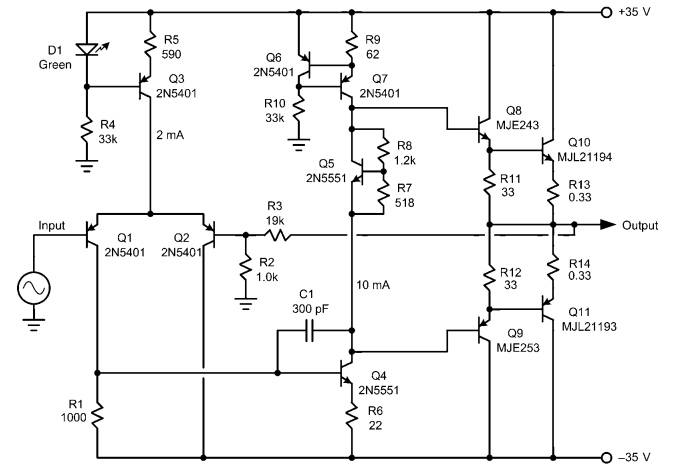
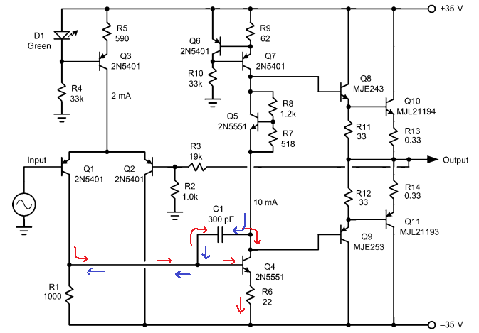
I have a question about the Miller capacitor in the attached schematic of an audio amplifier. I read from a book on audio amplifiers "At higher frequencies, virtually all of the signal current from the LTP (differential input pair) flows through C1". My question is: Where does this signal current go to? So the signal current flow though C1 and what is the current path of this signal ? Thanks.


It is negative feedback to the base of Q4.
The current is provided by Q1 which is driving Q4's base.
The negative feedback current through C1 is basically subtracting current from that which would otherwise go into Q4's base. That reduces the gain of the Q4 stage to a low value at high frequencies.
 
Do you mean the signal current only flows in one direction through the capacitor? Only from collector to base?
 

Do you mean the signal current only flows in one direction through the capacitor? Only from collector to base?
I don't understand you question. :???:
It's an AC signal so the current flows back and forth.
But the collector is supplying the current.
 
Yes my question wasn't very clear. I looked into the schematic a bit further. I drawed arrows (blue/red) on the schematic to indicate where the signal current flows. The red arrows indicate the signal current path where the compensation capacitor gets charged and the blue where the cap gets discharged. Can someone tell me if these are the correct signal current paths? Thanks!


Hi, I had a question about the calculation of HF gain in the attached amplifier schematic. I found the following formula for calculating HF gain of the first two stages (input pair and Voltage Amplification Stage (Q4)):

HF-gain = Gm/(w*C)

Gm = transconductance of input pair
w = 2 * pi * frequency
C = Capacitance of compensation capacitor (C1)

I would like to know why only the capacitance and input pair Gm is included as a factor for determining the HF gain. How is this formula derived? Thanks.


That equation is an approximation but it works well since the relatively large compensation capacitor response dominates the circuit frequency response and all other circuit capacitances are much smaller.
The formula is simply the frequency response of a grounded-emitter follower stage with a miller capacitor.
 

Status
Not open for further replies.

Similar threads

Part and Inventory Search

Welcome to EDABoard.com

Sponsor

Back
Top