Continue to Site

Welcome to EDAboard.com

Welcome to our site! EDAboard.com is an international Electronics Discussion Forum focused on EDA software, circuits, schematics, books, theory, papers, asic, pld, 8051, DSP, Network, RF, Analog Design, PCB, Service Manuals... and a whole lot more! To participate you need to register. Registration is free. Click here to register now.

Current mode Half Bridge converter.

cupoftea

Advanced Member level 5
Joined
Jun 13, 2021
Messages
2,589
Helped
54
Reputation
108
Reaction score
115
Trophy points
63
Activity points
13,602
Hi,
We all knew that Half Bridge shouldnt be done in Current Mode.
But with software to guide it, Current mode becomes possible.

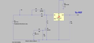
You simply repeatedly measure the voltage on each of the series stacked capacitors....(by using two potential dividers)...and then you slightly adjust the alternate duty cycles to correspond to the voltages on the series stacked capacitors.....then the volt.seconds remain balanced in the transformer primary...and the series stacked capacitors stay with the same voltage.

Say the bottom capacitor starts getting increased voltage...then you very slightly increase the duty cycle of the bottom FET....until the capacitor voltages re-balance.

Simple!
Would you agree though?

Attached is how to do it..LTspice and jpeg
--- Updated ---

I believe now we will see the rejuvination of the Half Bridge in the SMPS world...do you agree?.....no more two transistor forward...with its awful 50% duty cycle limitation, and having to switch the full 400V PFC bus...whereas a half bridge transformer only has to switch half of it.
--- Updated ---

And No more awful push pulls..with its huge double_Vin FET voltage when OFF....and the awful primary leakage and magnetising energy to dissipate.
--- Updated ---

I mean, by all means...do all the duty cycle extension in software if you want....cycle by cycle.
 

Attachments

  • Duty cycle extender.jpg
    Duty cycle extender.jpg
    91.2 KB · Views: 111
  • Duty cycle extender.zip
    875 bytes · Views: 75
Last edited:
Thanks, there is one massive worldwide-known power supply consultancy that is currently doing a single stage PFC'd SMPS , which relies on software to constantly balance the volt.seconds of their transformer primary.
They actually show the basic schem on their website...and you can see that it would need a lot more volt.second balancing effort than the half bridge which i show. They do all the v.us balancing in software.
 
You can actually use a small amount of current mode in an half bridge ( added to ramp ) and it will work just fine


There is an even better way - thought of decades ago: -

Use the Vin to power the cap for the ramp, this way if Vin goes up or down the ramp varies in the same ratio

this acts just like current mode - but better - as you always get a clean intersect even at low power

then if you run average current mode based on Iout - you get the best dynamics possible for the half bridge.

( you might note that any ripple on Vin is automatically cancelled using the above - in the same way current mode would ).
 
Use the Vin to power the cap for the ramp, this way if Vin goes up or down the ramp varies in the same ratio

this acts just like current mode - but better - as you always get a clean intersect even at low power
Thanks, i see your point.....will look into a good circuit to provide the ramp in voltage mode, in the way you describe.
 
As we know, pure current mode unbalances the capacitors, and they run away like positive feedback, the unbalance causes further unbalancing......whereas pure voltage mode acts to balance the capacitors...and imbalance in the cap voltages actually acts to right itself, due to the voltage mode.

When we have any current mode in there at all......we cannot keep the capacitor voltages exactly equal...there will be that bit of imbalance....maybe not much , but some.

I believe this is why we need the software.

Even in pure voltage mode, as you know, when it goes into overload, it can go into peak current mode because the current threshold (there has to be one somewhere) eventually gets hit.......so then we go unbalanced.

Yes we can do average current mode, but its extra componentry. To be honest, as long as we have some inner ramp caused by ramping current, then we are going to have some imbalance....even if we are regulating_the_output_current_to_regulate_the_output_voltage (as in average current mode)
 
Ah, no - the half bridge can tolerate some current information in the ramp without upsetting the rails - this is well proven

There is also a big difference between a " soft " center point of the rail splitting caps, and a " hard " center point - if you have a hard center point you can run current mode no problem.

I refer you to:

 
Thanks for the article, they dont go into the situation of overload , which could still imbalance the capacitors, despite their calculation..but i suppose they would say just use caps that can handle the full rail voltage.
--- Updated ---

Thanks, i did the calculation of the kindly provided article of #7 by Easy Peasy.

For Half Bridge
Vin=380V, Np/Ns=3.59, Vout = 37V, Pout=400W, Lout = 68uH, (Lp = 1mH), Tsw=10us

Equation 20 tells me that 0.64V of the 1Vpp control ramp can be from the current ramp.

However, the article also states that the answer is that the downslope should be injected on to the current signal.
This tells me that 0.672V of the 1V control ramp can be from the current ramp.

...so the equations dont quite agree....i suppose i would take the lowest current ramp contribution to be safe.

Interestingly, they dont consider the magnetising current at all in their equations.
--- Updated ---

Calculation as attached
 

Attachments

  • cap imbalance.zip
    8 KB · Views: 73
Last edited:
Thnaks for the Article, im going to have to go through it again....because if it were right, then you have to ask...why did Power Integrations make a chipset called HiperTFS for 2 transistor forwards.?.....when it would have been so easy to do a chipset for the Half Bridge?....and Half Bridge is better than 2Tran forward, due to longer duty cycle, less voltage gets switched , etc etc.

I mean, having said that, Power Integrations made the HiperTFS in Voltage mode anyway.
 
Two transistor forward has the same gate drive to both fets - 0 - 45% Duty - this is often favoured over the push pull drive needed for the half bridge

In either case the fets see only the rail volts - if clamping diodes used on the 2 sw fwd ( they always are )

The half bridge will give better input ripple and the Tx is fully utilised - whereas for the 2 sw fwd it spends half its time resetting - hence the Vout of the output wdg must be just over 2 x max required - so the diodes must be higher PIV for this ...
 
Thanks, ayk, with modern bootstrap drive ICs, the pushpull drive of half bridge shouldnt be such a problem?
In any case, the 2 sw forward would likely use a bootstrap drive anyway.....just not push pull type.

I think you said it well...and the benefits of HB over 2TF are plain to see.....its a mystery why Power integrations chose the 2TF for their HiperTFS range.......and made it work in voltage mode anyway!...they could have just used Half Bridge...though i suppose they must have been thinking about overload, where it goes into peak current mode.....but then.....HB with fully voltage rated rail splitter caps would still be better than the dreadful 2TF.
 
2 sw fwd is used in space apps where it doesn't matter if one device is triggered on by cosmic rays

in this respect it is more rugged and reliable than the 1/2 bridge

Some ultra reliable terrestrial designs use 2 x 2 sw fwd instead of H bridge for same reasons.

If you draw a 2 sw fwd with return diodes - it is essentially an H bridge with 2 sw removed but their diodes left behind - of course the Vsec wdg is twice the volts
 
Page 6 of the attached states (about half bridge)
3. The half-bridge converter does not work
well with current-mode control. Additional
circuitry must be added to balance the input
voltage on the divider capacitors

....this makes me a little sceptical whether this "current mode half bridge" thing really is genuine. If it was that simple, just adding a bit of slope, then Ridley wouldnt have bothered to bring it up.


Also, part 5 , page 6 states: (about half bridge)
5. During start-up, there will be asymmetry
in the primary voltage drives as the divider
capacitors adjust to split the input voltage.
This will place additional stress on the secondary
rectifiers.

...it doesnt go on to say that this can be mitigated by a simple little bit of slope compensation.

I am thus now sceptical of the article , kindly supplied, in post #7 above.
 

Attachments

  • incredible shrinking pow supply.pdf
    563.2 KB · Views: 93
Scepticism is a healthy thing - knowledge is even better - you must make your own choices based on the extent of your practical work achieved to date.
 
Thanks, wont get the chance to build it for a while.....suspect HB will be OK as long as splitter caps, and output diodes, are rated as if full rail was on a splitter cap.
The simulator should be able to answer this question too.........ill just set it up with one HB FET getting a slightly shorter pulse, and with added slope (obviously for both fets) , and see what happens....

Interesting one though, i remember Marty Brown, in Book "power supply cookbook" had a transformer with extra balancing coils to balance the half bridge splitter caps........when all he really needed to do was add a wee bit of slope?

Also, the HB is often done open loop with output inductor absent, and just big leakage inductance.......ie, not current mode......did have overcurrent limiting though, but that only acted when in overload. Have done returns checking for these PSU's.......one of them did have an appalling failure rate, (not the other though), but that was likely due to the 1 Amp ripple rated input capacitor, (for a 3kW supply)
--- Updated ---

Even Basso, on pg 94 of his book, "switch mode power supplies" says Half Bridge "caanot easily work with current mode".....article of #7 above, suggests it can.
--- Updated ---

Billings and Morey, in book, "switch mode power supply handbook", on age 3.153, show current mode half bridge needing a "dc charge restoration " circuit...involving an extra winding on the primary.....of Np turns, and two diodes at one end of it........this kind of complexity comes tantamount to total disagreement with the article of #7 above, which would totally remove the need for all that paraphinalia.
--- Updated ---

sorry....spelt "paraphernalia"
--- Updated ---

The solution of the top post would of course, introduce an effective DC current in the transformer...but that would be developing in there anyway.
--- Updated ---

The Billings and Morey solution says the extra primary winding can also give "leakage inductance energy recovery action"...but i think leakage L energy gets recovered to the splitter caps anyway in Half Bridge.
 
Last edited:
Not every one has done the practical work needed to prove some slope comp in the 1/2 bridge

( full slope comp does not - this is all some people know )

there is a lot of noise out there - some from respected players who have not addressed the topic too deeply ...

there is no substitute for either a) very thorough modelling with all parastics, or, b) real circuits.
 
Yes thats right, Dr Ray Ridley in the attached "the incredible shrinking power supply"...page 6, part 3, states

********************* QUOTE *****************************
3. The half-bridge converter does not work
well with current-mode control. Additional
circuitry must be added to balance the input
voltage on the divider capacitors
************************UNQUOTE ************************

...but as we see, just a little bit of slope comp and the 1/2 bridge is great for current mode......the "slope" added can simply come via some "natural" magnetising current ramp...no extra cctry needed at all.
 

Attachments

  • incredible shrinking pow supply.zip
    513 KB · Views: 60

LaTeX Commands Quick-Menu:

Part and Inventory Search

Welcome to EDABoard.com

Sponsor

Back
Top