Continue to Site

Welcome to EDAboard.com

Welcome to our site! EDAboard.com is an international Electronics Discussion Forum focused on EDA software, circuits, schematics, books, theory, papers, asic, pld, 8051, DSP, Network, RF, Analog Design, PCB, Service Manuals... and a whole lot more! To participate you need to register. Registration is free. Click here to register now.

current mirror Op-amp fully differential CMFB connection

Status
Not open for further replies.

Junus2012

Advanced Member level 5
Joined
Jan 9, 2012
Messages
1,552
Helped
47
Reputation
98
Reaction score
53
Trophy points
1,328
Location
Italy
Activity points
15,235
Hello

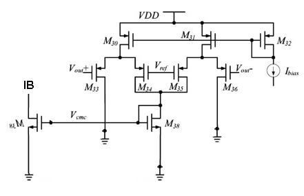
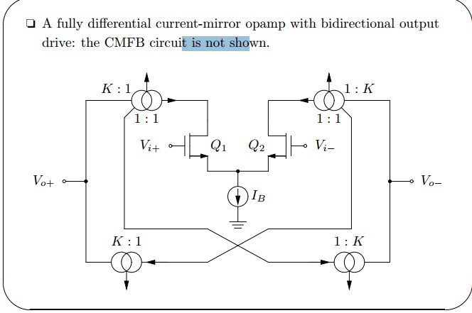
Could you please help me with this circuit. it is current mirror fully differential amplifier. I would ask your suggestion about the CMFB and how to connect it with this circuit, ist possible to connect the control from the CMFB to IBias ?


please I really nead your help and any suggestion is approciated
 

In the present circuit CM output is only ruled my current mirror inbalance, but not influenced by Ib. You would want to add auxilary current sources to control it.

Differential amplifiers with CMFB are discussed in recent analog design text books.
 
Dear FvM

Thank you for you reply

I have no problem with the CMFB circuit as you said it is available in many text books. consider please I would use the following CMFB, then how the connection will be with my OTA circuit ???

thank you for your reply
 

I am sorry I didnt attach the image of the CMFB from my previous post , now please refer to it

9490051300_1353004820.jpg


Now I will use the mirror the current from vcms directly to be the current source (IB)of the circuit. please correct me if I am wrong. the second thing please what the meaning of the auxiliary current source ??
 

As said, it doesn't work with the circuit from post #1. You should find out if you analyze it's operation. Ib is mirrored into both low and high side current sources, thus it doesn't change the current difference, at least for ideal behaving sources. You can change the circuit operation by e.g. adding a small positive offset currents to the high side current sources and reducing it's K slightly.
 
Thank you very much FvM,
it is very clear now for me.
Now I have to find like a CMFB that can do this. I dont know but usually I see from the papers that the CMFB work wit hthis circuit is switched capacitor CMFB and I never seen a C.T CMFB with this topology which I need. if you have any resource about it please tell me

thank you once again
 

Dear Fvm

I am sorry to disturb you again, I usually see that the CMFB for this kind of an OTA is implemented with SC CMFB not with continous time CMFB as shown with the attached image


where the control transistors of the CMFB are labelled with gate fb.

for me I am not intending to use the SC CMFB so Please do a favour for and help me to implement a CT CMFB for this circuit and again I am sorry to disturb you
Thank you very much
Regards
 

Considering the output polarity of your CMFB amplifier, you would place N-channel "FB" current sources at the low side, in parallel to m5a and m5b, controlled by Vcmc. To allow bipolar common mode feedback, you need to add a bias current at the high side, e.g. by adjusting the transistor areas or adding static current.
 
Status
Not open for further replies.

Part and Inventory Search

Welcome to EDABoard.com

Sponsor

Back
Top