Continue to Site

Welcome to EDAboard.com

Welcome to our site! EDAboard.com is an international Electronics Discussion Forum focused on EDA software, circuits, schematics, books, theory, papers, asic, pld, 8051, DSP, Network, RF, Analog Design, PCB, Service Manuals... and a whole lot more! To participate you need to register. Registration is free. Click here to register now.

[SOLVED] Current measure using CT

Status
Not open for further replies.

jay1691

Member level 2
Joined
Jul 22, 2014
Messages
47
Helped
1
Reputation
2
Reaction score
1
Trophy points
8
Activity points
345
I have a Current Transformer for 10Arms rating with 1:1500 turns ratio. I'm not familiar with it. In Current transformers the specifications will be in primary current to secondary current ratio, but here the ratio is in terms of primary & secondary turns ratio.
1. How to calculate the current ratio from turns ratio?
2. Is it 10 Amps differ from 10Arms?

Please some one provide a good signal conditioning circuit for the current measurement. The datasheet is also attached.

Thanks in advance...

I have Found below method. is it corect ??
:1500 is the turns ratio.10 Amps = 10A
See the equation
Np/Ns=Is/Ip

Ip =10 A(considered max)
Is = ?
Np =1 turn(cable through the hole)
Ns = 1500turns

Is=(Np/Ns)Ip
Is =0.0066A
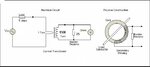
Burden resistance 75E
Out put voltage when 10A flowing through primary is 0.0066A*75E= 0.5V


Here my test Set up is below, Let me know if anything is wrong.
 

Attachments

  • CT1248-A1-RC_03.pdf
    345.4 KB · Views: 83
  • CT_Setup.JPG
    CT_Setup.JPG
    22.4 KB · Views: 92

Hi,

All seems to be correct t.

Keep in mind that the CT is for AC only.

Klaus
 

The current transformer is in fact a voltage transformer, the turns ratio define the voltage ratio.
Output voltage is then a function of input current, and must be calibrated. Therefore the meter connected to the CT is rather a milli- or volt-meter with indication proportional to input current. I never saw a CT working without calibration while voltage transformers simply work by turn ratio.

If one needs to measure a current with an ammeter, simply use a shunt. CT is suited for large AC currents and offers also a high-voltage insulation between the primary and meter circuits.
 

Hi,

The CT makes a true current-to-current transformation.

Voltage is undefined at a passive CT output. You always need a burden resistor.
Don't use a CT with secondary side high impedance.

We use CT for 10A up to 20000A in industry. We usually buy CT without the need for calibration.

Klaus
 

I bet no one tells you of the distortion of the CT output due to the magnetising current, and how dealing with this is something that you must always check.
Find attached knowledge about current transformers
 

Attachments

  • Current sense transformers.zip
    8.6 MB · Views: 67

Hello,

Thanks so much to all.
1) I have one question regarding Saturation Voltage Vmax for CT1248-A1-RC. As there is no information given in datasheet.
2) One more thing i have to clarify is that i will use that CT for measuring 0-2 A (A.C.) only, because i want high isolation from primary to secondary.
3) while i have taken practical reading with this set up i did not get any reading which is match to our theoretical calculation. so is that calibration is needed ?
4) what is limitation of primary turns for any CT ? It means how many turns i can wind on primary side on CT 1248 ? Is there any theory ?
 

Hi,

passive CT:
1) saturation: specified is 10A at 50/60Hz and 75Ohms burden.
--> don´t use more than 10A, don´t use lower than 50Hz, don´t use higher than 75 Ohms.

2) for 0..2A you my use max 5 primary turns, because 2A x 5 turns = 10A. The CT will see 10A. Don´t use more than 5 turns.

3) Datasheet says 0.2% amplitude error. If you read something worse you should review your circuit.

4) see 2)

Klaus
 

1) The remenance caused by saturation will cause errors for many cycles with a DC offset.
Then a random line reclosure will cause saturation again causing more errors from previous fault line opening with Remenance.
Thirdly, saturation from Burden R being too high.

ref https://www.google.ca/url?sa=t&rct=...C3MDl6oTb8pOZuouQ&sig2=eLS7TZ-4-gB2qdCJd8iipQ
2) n.c.
3) Show results, calculations and measurement method.
4) Primary Turns=1 for yours being 1:1500 , if you plan on using only 2A on 10A rated CT, you can use 5 turns but then lose on margin for above transients if that is important to measure startup current accurately.
 

I bet no one tells you of the distortion of the CT output due to the magnetising current

It´s not too rare to see many CT somewhat oversized to the power consumed by the load resistence. Should we assume that it is done to reduce the effect of the remansescent magnetism ?
 
Hi,

ideally the burden resistance should be zero. But with zero resistance there will be no voltage to measure.

With higher value burden there is more distortion and earlier saturation.

Klaus
 
don't know about remanence, but oversizing to make secondary turns have large inductance and low resistance so as to give less magnetising current distortion could be common I believe.
 
Hello,

Finally i got practical readings same as theoretical and clear about all quires which are listed above.

One last thing i have to ask,As i have shown in attached test setup in my first post ,
Is series resistor in primary side is really required ?
If yes , then Why ?
And how can i calculate the range of value for series resistor ?
 

The quantity measured by a CT is an AC current, not a voltage. Respectively I would use a current source in the test setup.

If you don't have a current source, use a voltage and a resistor. Ohm's law applies.
 
Dear FVM,

Specification is given below.
AC Current Input : 0-2A, 50Hz
So it may be directly current source from another sensor.
I have to sense 0-2A signal on my board which is coming from field and for that i am using CT 1248 current transformer.
So from your answer i can conclude that as my input is current source, there is no need of series resistor on my board.
Am i right ?
 

Status
Not open for further replies.

Similar threads

Part and Inventory Search

Welcome to EDABoard.com

Sponsor

Back
Top