Continue to Site

Welcome to EDAboard.com

Welcome to our site! EDAboard.com is an international Electronics Discussion Forum focused on EDA software, circuits, schematics, books, theory, papers, asic, pld, 8051, DSP, Network, RF, Analog Design, PCB, Service Manuals... and a whole lot more! To participate you need to register. Registration is free. Click here to register now.

Current limiting problem in linear regulators

Status
Not open for further replies.

kaveha

Newbie level 3
Joined
Jan 5, 2008
Messages
3
Helped
0
Reputation
0
Reaction score
0
Trophy points
1,281
Activity points
1,314
current limiting regulator

Hi,
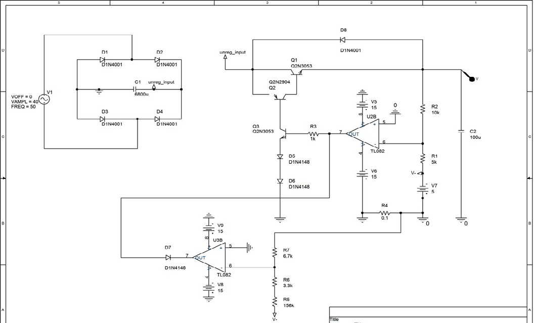
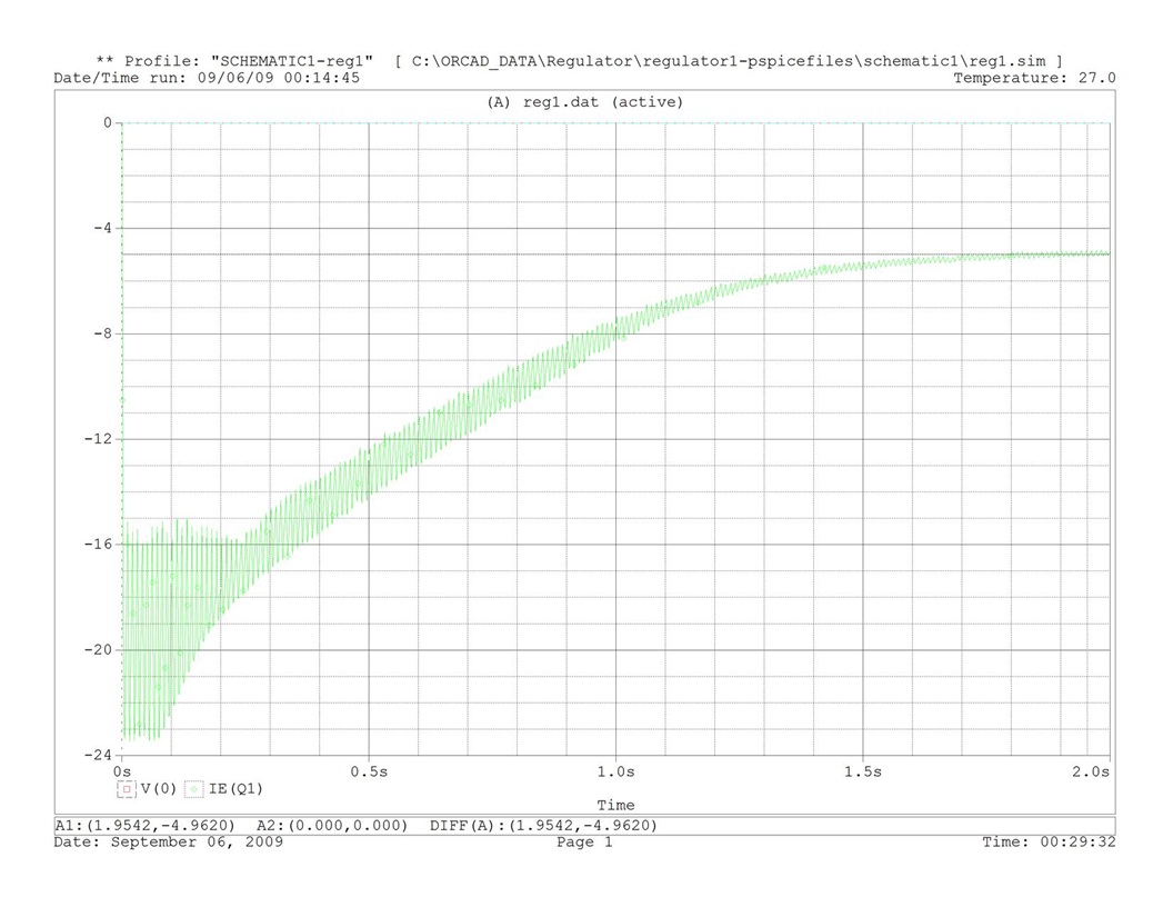
I have designed a 0-35V and 0-3A linear regulator using the classic circuits including opamps and power BJT's. After building the circuit, i saw that the voltage regulator works well but the current limiting circuit oscillates. it causes to fail power BJT's. I am trying to find a solution to solve this problem, and i would be glad if you help me?
I read the "Art of electronic" but its circuits could not help me.
 

regulator with current limit

using the classic circuits
That's no very specific in my opinion. Generally a voltage or current regulator involves a feedback loop, so it's not necessarily stable. They typically require a compensation to achieve sufficient phase margin and may have a limited range of allowed load impedance.
 

linear regulator range op amp

is it led driver

is this yuore problem...

**broken link removed**

the bjt's act like colpitts oscillators.........just put caps in to get rid of oscillation
 

current limiter bjt

thanks for reply
No, i just try to build a laboratory power supply. I have browsed the web and available books to build my own circuit not only a copy.
Please consider the attachment.

I used a 7805 (V7 DC voltage source) for reference voltage, U2B opamp for voltage feedback ,and U3B opamp for current feedback. R4 (0.1 ohm) is used to sense the current. R6 and R7 are used as a voltage divider circuit replaced with a 10k pot in the built circuit. the problem occurred when the voltage drop across the R4 changes the status of the U3B opamp to negative saturation (specially in short circuiting the output). this makes the pass transistors off and reduces voltage drop across the R4 and changes the status of the U3B opamp to positive saturation. these loops of on/off states cause to passing high current through the pass transistor.
It seems that Your idea about adding a Cap parallel to R4 is suitable. but there are two problems:
1. In circuits found by me there is not such cap and i don't understand how do their circuits work well?
2. It reduces the precision of limiter.

if you have and guidance on correcting this circuit please inform me and introduce me any technical book or paper including detailed expansion on this title.

thank you
 

linear regulator with current limit

As already said, a feedback loop compensation is most likely necessary. It could be needed also for the voltage loop, but that's a different story. I suggest a simple way to add a PI loop characteristic. You can empirically tune the R (P gain) and C (I gain).

Also I don't like your way to combine voltage and current loop. Basically both OPs are forced into current limit, I can't predict which one wins. By a simple modification you can solve this issue. But the current loop gain increases, which must be reflected by the compensation.

I assume, that for a perfect transition between current and voltage limited operation, additional circuit means are required. But you you should be able to achieve stable operation at least.


what is feedback compensation used for regulator

thanks again,
According to your suggestions, adding this RC compensator makes the circuit relatively stable but not precision (I simulated it few minutes ago). but i am not certain on reliability of this circuit because of its trouble transient response containing dangerous current spikes. below figure shows current plot of this circuit on short circuit condition. this is the best result obtaining by tuning the above mentioned RC.


I think your idea about disjointing the current and voltage feedback loop is good, but unfortunately i don't have any effective idea to implement it.

I'm looking forward to hear from you about references (Books , ...) if exist!
 

Status
Not open for further replies.

Similar threads

Part and Inventory Search

Welcome to EDABoard.com

Sponsor

Back
Top