Continue to Site

Welcome to EDAboard.com

Welcome to our site! EDAboard.com is an international Electronics Discussion Forum focused on EDA software, circuits, schematics, books, theory, papers, asic, pld, 8051, DSP, Network, RF, Analog Design, PCB, Service Manuals... and a whole lot more! To participate you need to register. Registration is free. Click here to register now.

current limiter for led driver (DC)

Status
Not open for further replies.

yoosefheidari

Member level 5
Member level 5
Joined
Aug 31, 2013
Messages
91
Helped
0
Reputation
0
Reaction score
1
Trophy points
1,288
Visit site
Activity points
2,051
HIi want to turn on 7-8 power led(1 watt) and i need a simple current limiter.
i have a 25.9v li-ion battery and need 350 ma for each led.
each led need 3.12v and led's are series.
i need a simple circuit with high efficiency.
please help me.
 

A basic current limiter s a series resistor. To save power, many LED drivers are now available that use PWM (pulse width modulation) to adjust average current through the LEDs.
Many good drivers are described in Edaboard and in most electronic magazines. Look at Maxim, Analog Devices and others for details.
thank you
but i am beginer
i need a current limiter circuit for 7-8 watt series led with high efficiency

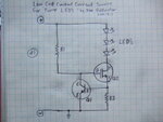
is this cicuit good?
it's efficiency?
power-led-driver-circuit.jpg
 
Last edited:

8 LEDs in series means you need 24.96V to drive them to full brightness, that's perilously close to the 25.9V of your battery. If you wire them in a single series chain you will almost certainly find their brightness drops quite dramatically as the battery starts to discharge and can no longer supply them. It will work with 7 LEDs but your margin is still slim. A better solution would be to wire them in two chains of 4 LEDs or even one of 6 LEDs and one of 2 so the voltage requirement is safely below the battery voltage.

As for constant current, yes the circuit will work, assuming Q1 is a small signal normal NPN transistor you want the value of R3 to be 1.8 Ohms (actually just over 1.7 Ohms but that isn't a standard value). you must understand that any linear current regulator will produce heat. The power loss will be the voltage dropped across it multiplied by the current passing through it so in your case if you use one of these circuits for each chain of 4 LEDs the power lost as heat will be the difference between battery voltage and LED voltage (4 x 3.12) = 25.9 - 12.48 = 13.42V multiplied by the current of 350mA 13.42 * 0.35 = 4.69W. Almost all of this will be in the MOSFET so it will need a finned heat sink to prevent it overheating.

Brian.
 
That circuit works quite well - I have used the all transistor version several times before - but it needs a couple of volts across it to work - like betwixt stated, you have too many LEDS and power dissipation to be concerned about. Not sure how you mean efficient[it is efficient in terms of required voltage across it], but it is effective.

say V+ minus current limited voltage drop > nbr of LEDS * Vd

[26 - 3 ] / 3.12 = 7 LEDS but don't forget that the battery voltage may drop
 
thanks alot
i use exactly 7 led so led's need 7*3.12=21.84 volt
my battery voltage in full charge is about 29.4 and when is empty about 25.9 so i think battery isn't problem and it's better that i wire led's in series.
but you say i have many power dissipation with these linear regulator.how can i drive led with minimum of power dissipation?can you give me a circuit for minimum of power dissipation?
 

5W of heat dissipation is not much, going to PWM requires a more complicated circuit................... plenty of PWM circuits around, though perhaps the simplest is based around the 555 - search the internet for "PWM 555" - usually the duty cycle is 50% to 99% although it can extended to 0% to 99% with a few more parts.
 
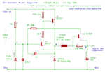
i found a circuit on net and i think this circuit is good for me.
how about this circuit?is it good?
3tran_br.gif
 

That's a good design, I like Roman Black's work but it's a constant voltage generator with current limiting, what you need is a constant current generator. The brightness of the LEDs is proportional to the current flowing through them but their Vf changes slightly with temperature and of course the battery voltage drops as it discharges. What you need is a device that drops a variable voltage in order to keep the load current constant, in other words, one that drops less as the battery voltage drops and allows it's output voltage to track Vf changes.

The classic method of generating constant current is to pass it through a fixed resistance so (Ohms Law) converts it to a voltage proportional to the current. The voltage across the resistor is then held constant by a feedback circuit. If the voltage across a fixed resistance is constant, so must the curent through it. This is what the circuit in post #3 does. The only possible improvement is to replace the linear pass element with a digital one but the circuitry quickly gets complicated. You might find help if you research "LED drivers" on manaufacturers data sheets (Maxim comes to mind), in particular the circuits for white LEDs although the color is irrelevant.

Brian.
 
thank you
i understand many things
for some reasons i decide to use 4 leds for my torch.i want use four 1watt leds that need 4*3.12=12.5 volt and fixed 350 mili amp and replace my battery by a 4 cell li-ion that is 14.8 volt when empty and 16.8 when is full charge.
so because roman black's cicuit isn't good for me i search for maxim led drivers and find max16818 and max 16834.but i think their output voltage is about 5 or 6 volt.is it right?
i need a cir circuit with 14 to 17 volt input and 12.5 to 13 volt output.can maxim ic's work with 14 to 17 volt input and give me 12.5 volt in output?what number of ic?
 

Both those IC are only available in SMD packages and the MAX16818 has no pins, it has to be soldered using special equipment so they may not be suitable for you.

The idea of a constant current generator isn't that it gives a steady voltage at it's output, quite the opposite, it's supposed to vary it's output voltage so it drives the same current into different loads. For example, if it had to deliver 100mA into a 100 Ohm load it would produce 10V but if you changed the load to 200 Ohms it would produce 20V instead.

If you are using 4 LEDs and a 14.8V battery I would suggest you try a simple circuit from here: **broken link removed** and set the current to 350mA. I use that circuit (it is from the data sheet) for portable emergency lighting here and it works well. Note that you MUST use a fast recovery diode in the circuit, a normal power rectifier like the 1N400x series will not work. Set the input voltage to your 'empty' battery voltage of 14.8V and set the output to the LED voltage 12.5V. The frequency isn't critical it just changes the inductor and capacitor values but pick somewhere between 10KHz and 25KHz.

Brian.
 
thank you very much dear betwixt
you learn me about smps.
i will use mc34063 for my emergency torch.
but in my searches on net i found this cicuit
https://s4.picofile.com/file/7920844294/2596_65_1301577300.gif
please tell me your idea about this circuit.is it a good current limiter for constant current?is efficiency more than 70%?
 
Last edited:

you are right.mc 34063 is very good but efficiency of this chip is about 60-70 %.
can i use a better chip such as LM2674 with 95% efficiency and few external component?can i use this chip as a current limiter?
 

You can use them as a current limiter but you reduce their efficiency if you do so. The figure they quote is as a voltage regulator. In order to regulate the output current you have to measure it, and that means a resistance has to be added in the output current path. The regulator voltage is then controlled to keep the voltage dropped across the resistor constant. The problem with this the resistor itself becomes part of the load and the voltage it drops is not available to the LEDs and hence reduces overall efficiency. You can minimize the voltage dropped by making the resistor value smaller but that also means you have less control voltage to monitor and an amplifier becomes necessary to bring it back to usable levels.

You should consider that a linear regulator will have an efficiency of less than 50% so anything higher than that is beneficial.

Brian.
 
ok
wath about these ic's?
max1776
max5033
max15014
and this one UC3842
are these high efficiency chip's linear current limiter or no?
 

No linear regulator can be more efficient than another. The power they lose is the voltage dropped across them multiplied by the current they are passing, these are decided by the battery and LED not the IC !

Brian.
 
THANK YOU
can you introduce me a good and simple refrence about switching power supply and regulators?i want learn more about switching
 

Status
Not open for further replies.

Similar threads

Part and Inventory Search

Welcome to EDABoard.com

Sponsor

Back
Top