chinwi85
Newbie level 4
Hello forum,
I am new with antenna and CST, sorry if there are some stupid questions;
In fact, I have a mini-project about simulating a pyramidal horn antenna, I don't know what exactly do, and what parameters should I play with to enhance the horn's gain, A great thanks for anyone can help me :
First, I have some questions:
- I don't know how to choose he range of frequencies for a given frequency,?
- Is the length of a waveguide affects (if too short or to long compared with the length of the horn), and how to choose it?
- I don't know about ports and modes, what influence occur with increasing/decreasing mode/port?
- what is the difference between the resonance frequency and the cut-off frequency, the latter should be within the range frequency?
- what is the mesh do exactly, why should I increase it's lines?
Second, I found this example:
<<Given: Gain = 20dB, Frequency =10GHz, (for example here what should the range of frequency be ???). The value of a (width) and b (high) of the waveguide part of the horn antenna are 6cm and 3cm respectively.
Calculated data:
Resonance Frequency = 5.59 GHz; A(horn's width) = 13.85 cm, B(horn's high) = 10.11 cm, L(horn's length) = 11.43 cm
The calculation of A, B and L, there is some parameter X to find first by iteration "I don't know how to calculate it :sad:", it is not detailed in the book "Antenna_Theory__Analysis_and_Design__3rd_Edition, Constantine_A._Balanis". if someone know how to calculate this parameter, please show some detail >>
Third, I putted the frequency range = [5,10], During the transient solver, The error show this "At least one propagating mode at port 1 is not considered in the time domain calculation! It might be better to increase the number of mode at port 1"
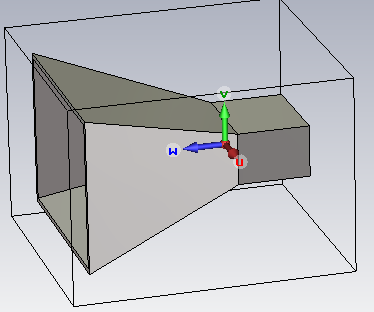
A picture of the model:
Please any help I will be very grateful;
I am new with antenna and CST, sorry if there are some stupid questions;
In fact, I have a mini-project about simulating a pyramidal horn antenna, I don't know what exactly do, and what parameters should I play with to enhance the horn's gain, A great thanks for anyone can help me :
First, I have some questions:
- I don't know how to choose he range of frequencies for a given frequency,?
- Is the length of a waveguide affects (if too short or to long compared with the length of the horn), and how to choose it?
- I don't know about ports and modes, what influence occur with increasing/decreasing mode/port?
- what is the difference between the resonance frequency and the cut-off frequency, the latter should be within the range frequency?
- what is the mesh do exactly, why should I increase it's lines?
Second, I found this example:
<<Given: Gain = 20dB, Frequency =10GHz, (for example here what should the range of frequency be ???). The value of a (width) and b (high) of the waveguide part of the horn antenna are 6cm and 3cm respectively.
Calculated data:
Resonance Frequency = 5.59 GHz; A(horn's width) = 13.85 cm, B(horn's high) = 10.11 cm, L(horn's length) = 11.43 cm
The calculation of A, B and L, there is some parameter X to find first by iteration "I don't know how to calculate it :sad:", it is not detailed in the book "Antenna_Theory__Analysis_and_Design__3rd_Edition, Constantine_A._Balanis". if someone know how to calculate this parameter, please show some detail >>
Third, I putted the frequency range = [5,10], During the transient solver, The error show this "At least one propagating mode at port 1 is not considered in the time domain calculation! It might be better to increase the number of mode at port 1"
A picture of the model:
Please any help I will be very grateful;