fangjing
Junior Member level 1
Hi all:
I am trying to reproduce the work from paper "Resonant metal-mesh bandpass filters for the far infrared" by D. W. Porterfield etc.
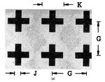
The geometry of the mesh filter is shows as below:

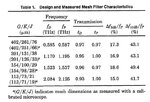
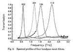
There are four filters considered in this paper (central frequency are 0.587, 1.195, 1.537 and 2.125 THz, respectively). The thickness of the metal mesh filter is not specified, I assume it is 10 um in my simulation. All the parameters are provided and the simulated resulted are presented in the paper as well:


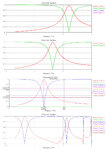
CST is used for the simulations. However, I am not able to obtain the same results as shown in the paper. I can have roughly same centre frequency for 113, 154 and 201 filters but the bandwidths are much wider than the results in the paper. For 402 filter, I observed higher order resonant in my CST simulation which is not shown in the paper, please see the figure below for my simulation results:

In the CST simulations, I set the boundary condition as below, and the modelling is provided. Only TE(0,0) and TM(0,0) floquet modes are used (which presents TEM mode plane wave excitation).

My questions are:
1. Why I cannot get the same results as shown in paper? I have a wider bandwidth and a central frequency shift ~ 0.1 THz.
2. I use TEM modes as the source. But for real measurement, higher modes may also propogate through this structure. Do I have to increase the number of modes in the simulation?
3. Is there any other way to model this structure? How to set the boundary conditions?
For your convienence, I also attached my cst file (NOTE that the parameter in my modelling is G, L, K instead of G, K, J in the paper)
Many thanks in advance.
Fangjing
I am trying to reproduce the work from paper "Resonant metal-mesh bandpass filters for the far infrared" by D. W. Porterfield etc.
The geometry of the mesh filter is shows as below:

There are four filters considered in this paper (central frequency are 0.587, 1.195, 1.537 and 2.125 THz, respectively). The thickness of the metal mesh filter is not specified, I assume it is 10 um in my simulation. All the parameters are provided and the simulated resulted are presented in the paper as well:


CST is used for the simulations. However, I am not able to obtain the same results as shown in the paper. I can have roughly same centre frequency for 113, 154 and 201 filters but the bandwidths are much wider than the results in the paper. For 402 filter, I observed higher order resonant in my CST simulation which is not shown in the paper, please see the figure below for my simulation results:

In the CST simulations, I set the boundary condition as below, and the modelling is provided. Only TE(0,0) and TM(0,0) floquet modes are used (which presents TEM mode plane wave excitation).

My questions are:
1. Why I cannot get the same results as shown in paper? I have a wider bandwidth and a central frequency shift ~ 0.1 THz.
2. I use TEM modes as the source. But for real measurement, higher modes may also propogate through this structure. Do I have to increase the number of modes in the simulation?
3. Is there any other way to model this structure? How to set the boundary conditions?
For your convienence, I also attached my cst file (NOTE that the parameter in my modelling is G, L, K instead of G, K, J in the paper)
Many thanks in advance.
Fangjing