DrunkBear
Advanced Member level 4
- Joined
- Dec 14, 2006
- Messages
- 108
- Helped
- 11
- Reputation
- 22
- Reaction score
- 4
- Trophy points
- 1,298
- Location
- HangZhou,China
- Activity points
- 2,115
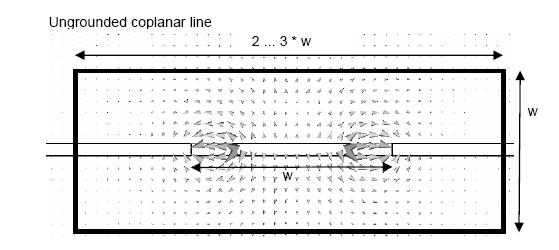
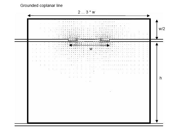
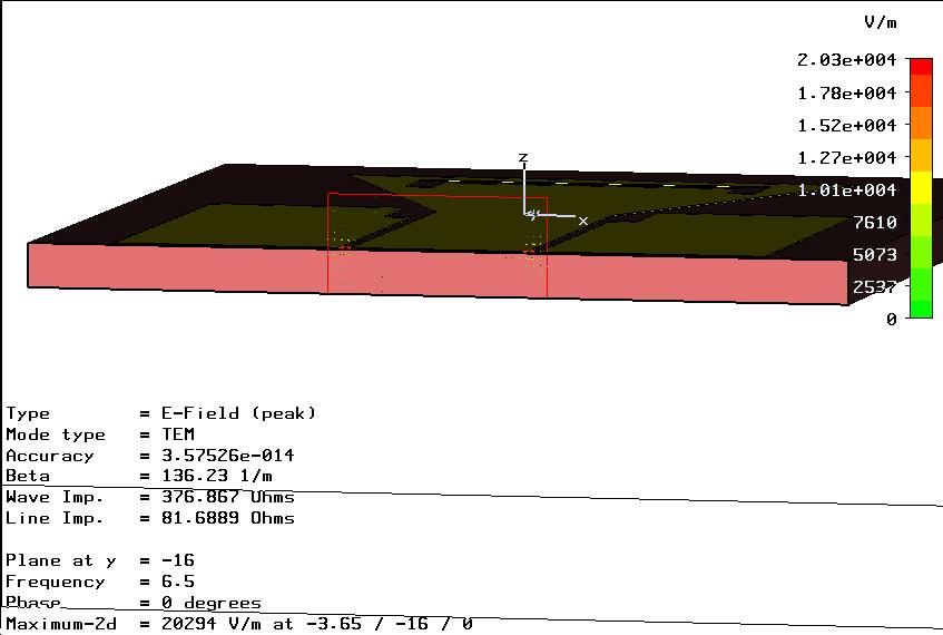
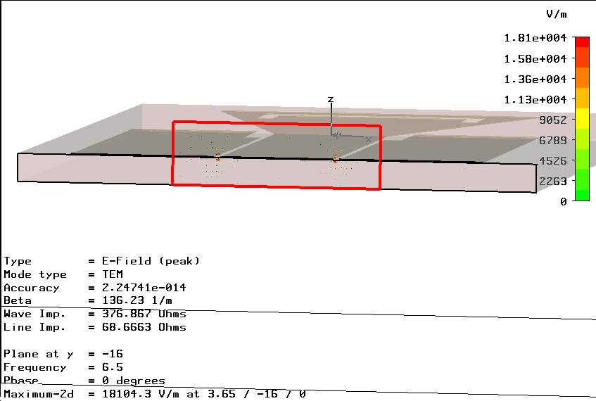
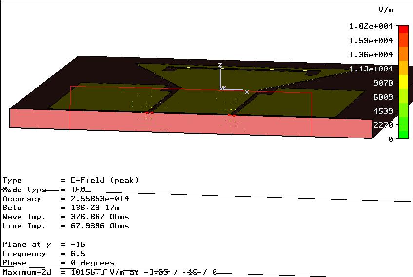
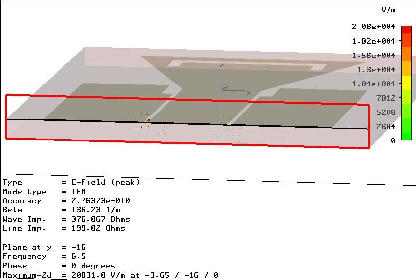
cpw 50ohm
Is there any principle, say the width and height, when setting the CPW port in CST.
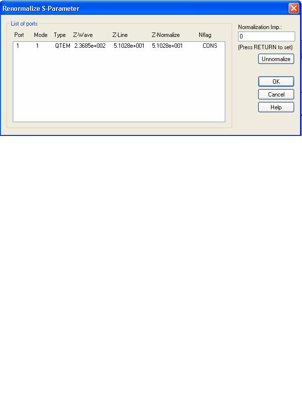
i noticed the quite different calculated Line Impedance is obtained for ports with different width.
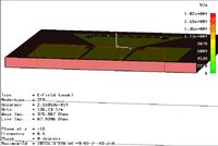
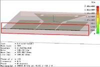
BTW, what does the following warning mean: "The degeneration of TEM modes at the homogeneous port 1 could lead to undetermined modepatterns. It might be suitable to define a multipin port instead" and what is its influence to the results?
Is there any principle, say the width and height, when setting the CPW port in CST.
i noticed the quite different calculated Line Impedance is obtained for ports with different width.
BTW, what does the following warning mean: "The degeneration of TEM modes at the homogeneous port 1 could lead to undetermined modepatterns. It might be suitable to define a multipin port instead" and what is its influence to the results?