Continue to Site

Welcome to EDAboard.com

Welcome to our site! EDAboard.com is an international Electronics Discussion Forum focused on EDA software, circuits, schematics, books, theory, papers, asic, pld, 8051, DSP, Network, RF, Analog Design, PCB, Service Manuals... and a whole lot more! To participate you need to register. Registration is free. Click here to register now.

CST antenna source & input impedance problem

Status
Not open for further replies.

gustavolsilvano2

Newbie level 4
Joined
Aug 5, 2011
Messages
7
Helped
0
Reputation
0
Reaction score
0
Trophy points
1,281
Activity points
1,355
Hello everybody.
I'm new in this forum and this's my first topic.
I'm from Brazil so excuse ne if I write something wrong.
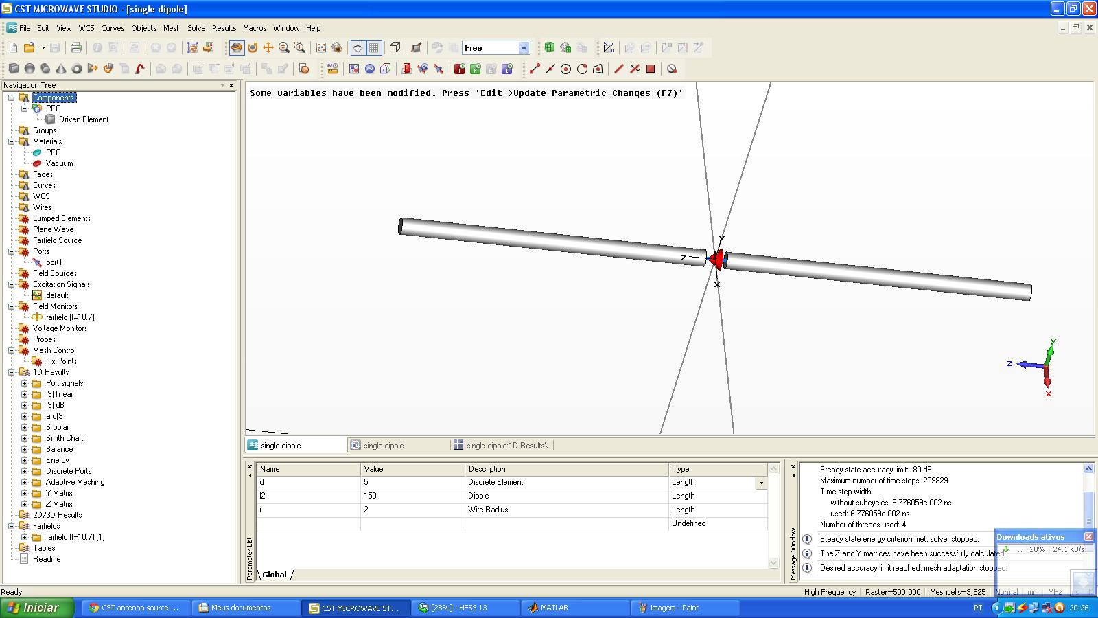
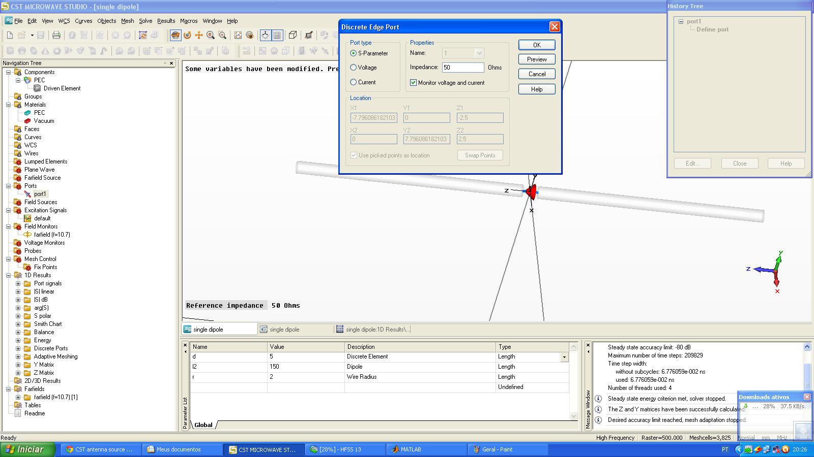
So my problem is that I want to insert an AC-voltage source in a dipole antenna.
Searching in the web I found that the discret port is the best option. Is that right?
If it is than I have a question. I have to put the dicrete port passing from the middle of the dipole (orthogonal to the antenna) or coming from one to the other antenna (parallel to the antenna).
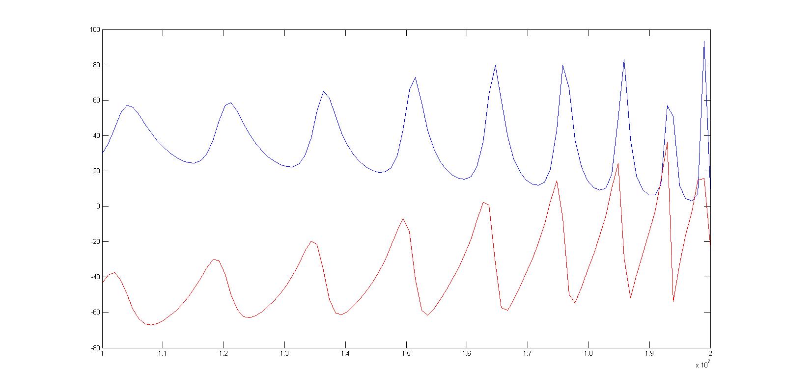
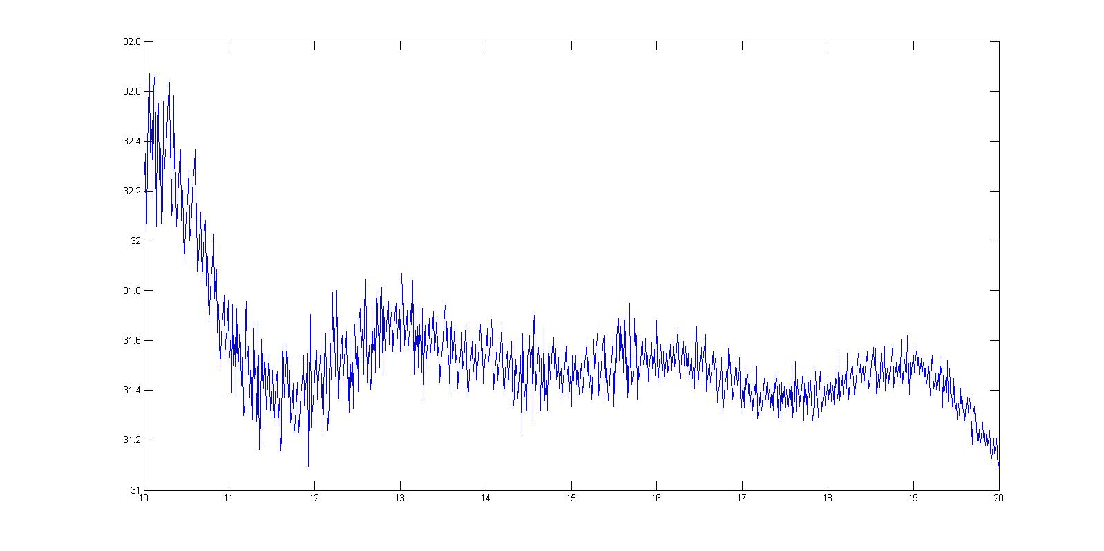
Another problem that I have is that I want to have the cst to plot the input impedance according to the frequency.
And the last problem is that I want to know the magnitude of the current so that I can calculete the input impedance (Zin=V/I) once that I know the voltage because I define it in the discrete port.
Thats all for now.
Thanks
 

hi
i cant understand some part of your question but u can use lamp port for CST and define your frequency in main page
for more help i suggest you to search in CST help in folder which you install CST there
u can find a yagi antenna for 33GHz which excited by model you need and u can alter it your demand
 

Can you say what you dont understand in my question so then I can explain better to you. this is a project and i have to finish till the end of the month
thanks
 

hi
the attachment contain a dipole antenna in CST
 

Attachments

  • single dipole.rar
    391.4 KB · Views: 106

This file is an example that comes together with cst and it have a discrete port. I want to know if this discrete port can be considered as a ac-voltage source. And another question is if in the cst I can have yhe graphic of impedance vs frequency cause I just can see the graphic of admitance vs frequency.
tahnks
 

As far as plotting the Admittance vs. Frequency... just export the Impedance vs. Frequency data using a Touchstone file (.S1P or .S2P) then import the data into some software and just take the inverse of the Impedance to get Admittance... Y=1/Z
 
CST can calculate and plot the impedance.
I think under Results->S-parameter Calculations->Calculate Z and Y Matrices. Then you should get two new folders in the 1D results, one for the Z- and one for the Y parameter.

---------- Post added at 09:06 ---------- Previous post was at 09:05 ----------

Another way for getting the input impedance is using the smith chart. You can add a marker for the desired frequency and CST will show the impedance at this frequency
 

I first want to thank everybody that are wasting their time solving my problems.
Thanks a lot!
Until now everything that i asked was solved. But I'm having some problems in my simulation.
Let me explain everything.
It's a dipole problem, and I have the parameter of the antenna (length, width,...) and the frequency bandwidth.
I have to find the input impedance and compare to the graphic that was calculated in a program in the matlab.
But it isn't matching.
The antenna has 7,25m of length each one, 2m of radius and 5mm of a gap between the two antennas. The gap have a discrete port coming from one antenna to the other.
The discrete port is an S-parameter of 50 ohn. The frequency range is of 10Mhz to 20Mhz. I'm using the transient solve and calculating the Z matriz, and using the same to calculate the input impedance using the matlab. The antenna is made of PEC. I'm using the "single dipole" example that already come with the CST, just changing the paramenters.
I'm attaching some pictures to ilustrate the problem.
That's all.
Thanks.
 

I think the main issue you are having is that your port is not setup correctly. The discrete port, which is a lumped element between the two points, should be used to excite signal path and return path (ground). This type of port will introduce distortions into the calculations. I would recommend trying a discrete face port, which is defined using an edge and another surface. Therefore, select the edge of the circle and the surface of the pole.

Also, don't you want to excite the dipole this way? I don't have much experience in antenna design but shouldn't you excite both poles at the same time?
 

I think you could do the simulation as shown in the pictures. The lumped port should be suitable for this.
Unfortunately the graphs haven't a label, so it is not clear what value is depicted.
Have you checked your farfield? Looks it like the typically dipole farfield?
Perhaps the 5mm gap is a little small for a structure of 7.25m. Then a huge mesh is needed to model the gap. Perhaps you can increase the gap?
 
Status
Not open for further replies.

Part and Inventory Search

Welcome to EDABoard.com

Sponsor

Back
Top