Continue to Site

Welcome to EDAboard.com

Welcome to our site! EDAboard.com is an international Electronics Discussion Forum focused on EDA software, circuits, schematics, books, theory, papers, asic, pld, 8051, DSP, Network, RF, Analog Design, PCB, Service Manuals... and a whole lot more! To participate you need to register. Registration is free. Click here to register now.

Crystal filter on the cheap

Status
Not open for further replies.

dr pepper

Advanced Member level 1
Joined
Mar 15, 2010
Messages
420
Helped
34
Reputation
68
Reaction score
40
Trophy points
1,308
Location
lancs
Activity points
4,128
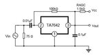
I'm throwing together a simple receiver using largely a Ne602 and a Ta7642 for am/cw demod and agc.
Between the '602 and the '7642 I'm using a single 3.579Mc colourburst crystal as the IF filter.
Ladder filters seem to use a cap between the first xtal, and the last xtal to the amp stage, with the caps to ground inbetween, to load the xtals.
Fiddling around I found that one 33pf from the o/p side of the xtal to ground works the best, a 15pf in series with the i/p and o/p seems to raise the stopbands to the point where they are clearly audible.
Whats the difference inbetween having a cap on the i/p and o/p, and just one at the o/p.
 

Depends by the impedance which the filter see at its input and output.
The output impedance of NE602 is about 1k when the input impedance of TA7642 is in the range of tens of kilo ohms.
Ideally would be to measure all the impedances and calculate an impedance matching network, for both, input and output of the filter.
 

Yes the o/p of the '602 is 1k5 unbalanced.
I cant find reliable data on the '7642, some say its 1m ohm, some 100k.
I fiddled around and loaded the input of the '7642 to ground with a 10k resistor, it works much better, varying the 10k varies the bandwidth as expected.
I have a micro vna but it doesnt 'like' the '7642', probably getting some dc voltages from it, maybe the agc.
Any ideas on working out the i/p impedance of the '7642'?, I can shove the thing in some bredboard and apply some modulated rf from my sig gen and look at the audio out.
 

TA7642 have an emitter follower at the input (pin 2) which is DC biased with a 100k resistor, so the input impedance would be less than 100k, I guess in the range of tens of k'ohms.
Adding resistors at input and output of a crystal ladder filter should be fine. Their values could be find experimentally. For best impedance matching have to use LC components.
TA7642 input (pin 2) have DC on it, so for VNA measurements must use a DC blocking capacitor (0.1uF).
Because TA7642 is just a multi-stage amplifier, do the VNA measurement of the filter together with TA7642 (one port to filter input, and one port to output of TA7642). But for this have to remove the 0.1uF shunt capacitor at its output (pin 3), and add a series DC blocking cap (0.1uF). In this way you know exactly how the impedance matching between filter and TA7642 behaves.
 

Attachments

  • ta7642.jpg
    ta7642.jpg
    11.7 KB · Views: 81

Yes I understand a reactive network is required for good impedance matching, however I'll use resistors if I can get away with it.
My vna does not like the IC, even with dc blocking caps, I used a resistor sub box and a modulated rf source, the highest o/p from the '7642 is when I have 10k loading the input to ground.
I think your probably right about the '7642 having an impedance of around 50 - 100k, I think I dervied 10k because it widens the bandwidth, if I was to perfectly match the impedances the xtal bandwidth would probably only be 200hz or so.
I'm going to experiment using a mc3361 product detector chip instead of the ta7642, then I can pick up Cw and Ssb.
 

Yes, MC3361 would be better choice...
 

Initial testing with the mc3361 I got excellent results on cw and ssb, good volume on am but lots of distortion.
To pick up am I'm using a 4.43mc xtal with the mc3361 slightly detuned from the IF filter freq to produce a audio beat note, and a varicap diode for fine tune on ssb.
But I've only spent an hour so far, I think the distortion might either be clipping or an impedance mismatch.
Handy function with the '3362 is squelch control, and a 'tuned' ttl o/p.
 

I did away with the ta7642.
I connected a 33pf to the o/p of the ne602, then through the xtal and finally another 33pf to the i/p of the mc3361, works well now.
A fine tune for the bfo isnt required, the local osc can be tuned to create a beat tone with the bfo for cw, and for am or ssb (more like dsb) the local can be tuned so the IF is the same freq as the bfo eliminating the beat note, I thought the local osc being lc would drift and create an unwanted beat tone on am after its runs for a a while, but this doesnt happen, maybe the local is being influenced by the IF or the bfo and syncing to it, or maybe the components are good enough to be stable.
For an ultra simple receiver it works very well, there doesnt appear to be much imd, and it goes down to Vlf, bandwidth is just wide enough for speech (not so much music).
Not sure whether I'll just add a couple of varactors / pots for tuning, or add an arduino and a si5351 dds and lcd / rotary encoder, the dds would delete all the comps for the local osc and the bfo as its triple channel.
 

Using si5351 would be a good choice, which can provide 3 variable frequencies, two in your case, the VFO and the BFO.
si5351 is not DDS but its a PLL, which actually is better because DDS have a lot of in-band spurs, which are hard to be filtered.
On the net are many projects with si5351 using Arduino, and the one from VK3HN is one of them. Have S-meter, CW keyer, and use an OLED display:


I'm not an expert but I've used the '5351 before, I thought it was a Pll and a dds, I get that lack of phase noise caused by changing count values for non integer divisors improves the harmonics.
I threw together a project that calibrates the '5351 to gps, its not super accurate but it works.
That rx'er looks quite complicated, I'll check that out when I get home.
 

I did away with the ne602 as well.
The osc in the mc3361 is now the local osc, I put the colourburst xtal between pins 3&5 as per normal if filtering, instead of the fm quadrature coil on pin 8 I built a simple one tranny osc with another colourburst xtal, and fed this to pin 8, making a superhet follwed by a kinda direct conversion IF.
It works, but theres a fair amount of noise, probably caused by the limiter gain, and the audio is quiet, the detector is meant for fm after all.
Nonetheless its interesting I got it to work with just the '3361, it picks up cw signals my uniden scanner cannot.
I think I'll tap off the IF from pin 5, the o/p of the if filter and feed that to a fet follower into some kind of am detector, and switch between it and the audio out of the 3361 as a am/ssb, cw switch.
 
Last edited:

I found a couple more things, 1 the op amp or filter amp as mc call it is pants, thats where the noise is comming from, maybe its the way I'm using the chip, an external lf358 is far better, 2 the detector seems to work with or without the bfo, and without theres no drift so it has a switch to switch it out.
The rx now works well with just the mc3361 and can pick up am, cw and sideband (both), and a mosfet, 2n2222 and a Lf258, I might put a couple of trannies on the other half of the op amp chip and use that to drive a little speaker.
 

Attachments

  • Image (5).jpg
    Image (5).jpg
    619 KB · Views: 158

Your schematic looks pretty much as the one I attach.
On your schematic you forgot to add the source decoupling capacitor of the J112 JFET. If the capacitor is not there, you will loose a lot of sensitivity.

Looking to the block diagram of MC3361 I see that both schematics use the internal limiter amplifier of the MC3361. Limiter amplifiers can be use only on FM receivers. The SSB and AM signals will be distorted when pass through a limiter amplifier.
Anyway, myself I would try to pick the IF signal after the IF filter, use an IF amplifier followed by a proper product detector made with ring diodes or a dual-gate MOSFET.
 

Attachments

  • mc331.gif
    mc331.gif
    29.3 KB · Views: 323
  • block.gif
    block.gif
    31.8 KB · Views: 125

Yes, interesting schematic, I should have started with that.
If you look I forgot the bias resistor from the bfo tranny base to +v, and the 33pf load for the IF filter xtal.
I forgot to add the decoupler on the fet front end, I'll try that, hopefully it wont overload the front end.
The limiter amp distorts on am badly as one might expect, on cw though it works well, theres no audio so it doesnt seem to ruin things.
However the filter amp according to the data sheet is for audio not rf and doesnt limit, your schem shows it as a audio filter but all the gain comes from the following transistor gain stage, I've seen them with a switch for narrowing the passband for cw, I think theres a max suggested o/p voltage I think thats my distortion problem.
I ended up doing pretty much as you would, for am I now have a Ta7642 which does a good job of demodding the rf and has agc, it taps off from the o/p of the IF filter, I have a switch that selects am audio from the '7642 and cw from pin 9 of the '3361.
I've been experimenting tuning a 10.7mc IF trans to 4.43mc and switching it in place of the xtal for wide band a,m.
I'm going to see if i can use the squelch module in the '3361.
 

Reading the datasheet for the '3361.
Audio output voltage for the filter amp 160mV, presumably this means maximum, my setup o/p's more, no doubt this is the distortion, less gain req.
The detector clips with a 2uV i/p, so either nothing or clipped.
I tried bypassing the 1k on the i/p fet, totally overdrives the mixer, I could put a bypass cap in series with a pot for Rf gain here, cant do much with the 1k as it sets the dc bias voltage for the fet's idss, the drain resistor gives an approx impedance match for the mixer, but it seems to work Ok, the strongest signal I can get on am is radio 4 on 198kc, and theres no distortion from the o/p of the IF filter.
 

Status
Not open for further replies.

Similar threads

Part and Inventory Search

Welcome to EDABoard.com

Sponsor

Back
Top