Continue to Site

Welcome to EDAboard.com

Welcome to our site! EDAboard.com is an international Electronics Discussion Forum focused on EDA software, circuits, schematics, books, theory, papers, asic, pld, 8051, DSP, Network, RF, Analog Design, PCB, Service Manuals... and a whole lot more! To participate you need to register. Registration is free. Click here to register now.

Creating an automatic 12 volt light dimmer.

Status
Not open for further replies.

Mighty_Pooh

Newbie level 3
Joined
Jun 16, 2015
Messages
3
Helped
0
Reputation
0
Reaction score
0
Trophy points
1
Activity points
25
Hi there people.
I have been searching all morning on how to create an automatic light dimmer.
By automatic i mean when the power is turned on the dimmer should dim the lights up slowly.
Right now i building a simple circuit for a raspberry Pi but it would be cheaper to have a system that doesnt require a raspberry, since i have a timed 220v switch that will turn on the led system i just want to put my light dimmer in between the 12volt transformer and the led to dim up nice and easy.

Can any one point me in a direction on where to learn about this?
 

Hi,

A schematic could clarify...

Do you want a phase control for your 220V AC?
Or do you want a phase control at 12VAC output of transformer?
Or do you want a soft start circuit in the DC path of the LED?


Klaus
 

lysdæmper.png

I would want to make a soft start circuit(i didnt know that was the name). But if i can make some kind of power charging in it so it would be able to dimm off as well as dimm in.

I hope the picture helps.
 

Hi,

still a question...
* Usually a transformer has AC output, (but there are electronic transformers with DC output. Especially for LEDs there are different LED drivers. Some are current controlled, and/or somehave PWM brightness control)
Maybe you can attach a datasheet or a picture of your transformer..

* but LEDs and LED stripes usually work with DC (But also here there are different types.. Some for voltage control, some for current control, Some are made to work on a 12V AC system...)
Please give technical data on your used LEDs.

Klaus
 

Its AC input and DC output as i live in Denmark. The transformer is 220v AC input, 12v DC output. 2 Amps output. I have this light dimmer attached right now it works but it does not do the job automaticly. **broken link removed**
 

Did anyone notice the wires are the same colour on both sides and the text description is reversed for each side?

If it was reverse connected, I wonder if it is protected for this scenario from destructive failure.


Murphy's Law, if anything can be backwards, it will be.
 

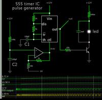
This concept might help. The 555 IC can be made to generate pulses of increasing duty cycle.

On powerup, C1 starts charging.

By applying the increasing voltage to the 'ctrl' pin of the 555, it lengthens the duty cycle.

(Op amp gain may be adjusted to create the correct volt ramp-up curve.)

Eventually C1 reaches 12V, and the 555 outputs a continuous high volt level.


The timeframe shown is 33 seconds.

This is only a conceptual schematic. Naturally you will need to adjust values to suit your desired pulse frequency, ramp-up period, led current, etc.
 

Status
Not open for further replies.

Similar threads

Part and Inventory Search

Welcome to EDABoard.com

Sponsor

Back
Top