Continue to Site

Welcome to EDAboard.com

Welcome to our site! EDAboard.com is an international Electronics Discussion Forum focused on EDA software, circuits, schematics, books, theory, papers, asic, pld, 8051, DSP, Network, RF, Analog Design, PCB, Service Manuals... and a whole lot more! To participate you need to register. Registration is free. Click here to register now.

Create 50-60Hz positive pulses from mains, using only transformers?

Status
Not open for further replies.
HTML:
Ok. Suppose the transformer is a 1 kW isolation transformer with E-I laminations, loaded as I described in post #12. Typically, what DC current would one expect in the primary?
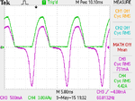
It depends on the nature & size of the DC load on the sec.
.

The load is a 50Ω in series with a diode. What DC current in the primary would you expect in this case?
 

unfortunately we have steel cored transformers which are non linear...
I know well. But some contributions in this thread seem to suggest that the asymmetrical secondary current would be somehow "reflected" to the primary without the working of a non-linear core. I just wanted to clarify that this doesn't happen.

An additional remark about core flux depending on "voltage or current". In fact, it can be calculated either as a function of voltage integral or magnetizing current, in the latter case translated by the core B/H characteristic. When DC magnetizing current is applied to the core, as in this case, you get more accurate results when putting the DC current in the calculation, I think.
 

FvM is correct, the magnetising current caused by the applied volts causes the flux, no current = no flux. A linear transformer assumes a core with no saturating characteristic, as we have to have a core to keep the magnetising current down, we never get the linear behaviour in the real world...
 
Hi,

the magnetising current caused by the applied volts causes the flux, no current = no flux.

you can find an equivalent circuit diagram of a transformer.
there are two vertical paths. One is the "optimal transformer" carrying the secondary current (divided by the turns ratio)
The other is the magnetic core (plus magnetizing loss R).

Then from input there is a horizontal RL (a part of the wiring copper R and a little stray inductance L), both are very low giving an impedance in the mOhms.
This impedance is influenced by the secondary current, causing a voltage drop. This meansthe core sees less voltage when transformer is loaded.
This also means the voltgae across the core is less when transformer is loaded. And because the voltage is lower --> also the magnetizing current should be lower.

*****

Let´s use a typical 500W/230V (primary) transformer.
Unloaded it draws only 80mA,
Connected to 250V it draws 120mA because of saturation effects. And you can see the distorted waveform at the ouptput.

But at full load it draws more than 2A. What about saturation now? And with this 16 times the current.. is there 16 times the saturation? And what about distortion of output voltage now?

Does the reality meet your expectatins?

Klaus
 

But at full load it draws more than 2A. What about saturation now? And with this 16 times the current.. is there 16 times the saturation? And what about distortion of output voltage now?

Does the reality meet your expectatins?
Maybe it's only me, but I really don't understand what you are pointing at.
 

sorry Klaus, those of us who have the benefit of an engineering degree know that the secondary ampere turns all but cancel the primary ampere tuns, leaving the same magnetising current in the driven (primary) winding, causing the same flux whether loaded or unloaded....
 
Hi,

Maybe it's only me, but I really don't understand what you are pointing at.

I just wantet to point out, that i am convinced, that the flux of a transformer core has a very good realtionship to voltage, and only a marginal realtionship to secondary current.
This marginal influence depends on stray inductance (in the range of nH), ohmic resistance of winidngs (mOhms) and source impedance (unknown).

For sure, i may be mistaken, but i have developed a lot of transformer circuits in the past 20 years.
And especially the experience with many different kind of transformers from small ethernet up to big 3MVA (where we built a softstart unit including remanence compensation)
.. it all showed the same behaviour. And it does all meet my understanding of transformers.... this is what makes me very sure about it...

i hope nobody feels upset because of my postings..

Klaus
 

Hi,

I just wantet to point out, that i am convinced, that the flux of a transformer core has a very good realtionship to voltage, and only a marginal realtionship to secondary current.

This not true for the case where there is DC current in the secondary. In that case, the secondary DC offsets the minor hysteresis loop which the core flux traverses, and the primary AC voltage does not constrain this offset.

I used a 96VA transformer (rated 8A at 12V) for an experiment. With a large Schottky diode in series with an approximately 2Ω load resistor connected to the secondary, the measured secondary current was 3.18A RMS AC only, 2.62A DC only, and 4.14A RMS AC+DC, measured with a Fluke 189 DVM. Here's a scope capture of the primary current (purple) and the secondary current (green). I used a precision 1Ω sense resistor in series with the primary to measure current, and a Fluke clamp-on probe to measure the secondary current for scope presentation:

attachment.php


At the right edge of the image are seen the primary and secondary currents as measured by the scope (True RMS, AC+DC of course). The values are slightly different than the values given by the Fluke 189, but they confirm the 189 readings.

The primary current is very unsymmetrical due to saturation of the core. The transformer is buzzing with a secondary DC current which is a significant fraction of the transformer's rated secondary current.

To measure the DC current in the primary, I used the Fluke 189 to measure the DC voltage across the 1Ω resistor which was in series with the primary. Setting the 189 to the 50 millivolt DC range, I saw an unstable reading of a few millivolts (corresponding to a current of a few milliamperes), bouncing around from positive to negative.

The scope capture shows an unsymmetrical primary current with a positive maximum of 1 amp and a negative maximum of 1.8 amps.

Trying to measure a DC current of a few milliamperes when such a large AC current is superimposed is going to overload the DVM if the DVM is set to a sensitive range. The overload will probably be unsymmetrical, giving rise to an apparent (but false) DC reading. No wonder I couldn't get a stable reading.

I realized that using a digital meter wasn't going to work, so I connected a sensitive analog millivoltmeter across the 1Ω primary sense resistor. I tested the sensitivity of the millivoltmeter and using a magnifying lens to observe the movement of the needle while injecting a current of 1 mA and also .1 mA into the 1Ω primary sense resistor. I found that I could easily detect .1 millivolt, which means that I could detect a primary DC current of .1 mA with this setup.

With this analog millivoltmeter, I saw no DC offset in the reading. However, the sensitivity was such that the needle bounced around a bit, due the random variations in the magnitude of the grid voltage.

I conclude that drawing half wave DC pulses from secondary of a transformer does not cause any DC in the primary. I don't know why it should. Even though the primary current is asymmetric, the area under the positive and negative lobes is equal. There is no magnetic rectifier.

It should be noted that the only way to get DC in the primary is for some rectifying action to take place in the copper circuit. Copper oxide can provide a rectifier as has been known for a long time, so if a copper wire with copper oxide on it is used to make a bolted (rather than soldered) connection, we might expect to see some DC in the primary due to the rectifying action of the copper oxide. Any presence of an asymmetric (piecewise linear or non-linear) I-V characteristic in some part of the copper circuit (such as an actual diode, of course) could produce DC in the primary, but non-linearity in the core won't do so.
 

Attachments

  • TranDC.png
    TranDC.png
    16.5 KB · Views: 133
In this instance I agree about the DC in the primary, the peaky current is causing similar net IR drop in the wires feeding the primary on its half cycle as the asymmetric load is causing on the less peaky half cycle, it would be interesting to see if this effect is maintained for a lower Vac primary such that the transformer does not get any where near saturation under normal operation. The transformer used clearly fully uses the core under nominal mains applied (as do many commercial designs), Well done to The Electrician for this post...
 

Hi,

Thanks Electrician for spending your time doing that test.

Especially your results for DC voltage components in the primary side makes me rethink my conviction of transformer primary current.
I'd like to apologise to all readers here that i confused with my postings..

So i have to do my homework doing some tests on this. Not that i don't believe in the results of the electrician.
But i need to understand why - and how - this meets my experience.
Ther are mainly two points for me to test:
* the temporal change of primary DC current
* and how this fits to a flyback transformer, where i also ( maybe wrongly) expect DC input current..

I wll post my results...

Another question is if we should open another thread on thus, because it is off topic somehow.

Again: sorry.

Klaus
 

I conclude that drawing half wave DC pulses from secondary of a transformer does not cause any DC in the primary. I don't know why it should. Even though the primary current is asymmetric, the area under the positive and negative lobes is equal. There is no magnetic rectifier.
Yes, thank you for insisting.

The inability of a transformer to transmit DC current can be seen in the equivalent circuit. To achieve a DC primary current and a respective voltage drop at Rs, either the input voltage or the voltage at Lh must have a DC component (a nonzero voltage average). But despite asymmetric currents and possible core saturation, the average voltage across Lh is always zero. So the DC current path from the secondary to the primary (and vice-versa) is blocked.
 

I would say that another thread would be a good idea.

Do some experiments yourself. You'll see that you won't get large DC currents on the primary, but you might get a few milliamps. This could be due to other half wave loads on the same circuit powering your transformer. Hair dryers on medium power show a large effect.

I tried putting a non-polarized capacitor made of two electrolytics back-to-back in series with the primary. But, unless the two electrolytics are absolutely identical, which they won't be, they will act as a slight rectifier.

Other effects such as the copper oxide coating on wires I mentioned could produce a little DC.
 
  • Like
Reactions: FvM

    FvM

    Points: 2
    Helpful Answer Positive Rating
The transformer in effect does transmit, or provide, DC at is output with a single diode rectifier, just as there can be a bit of DC in a switchmode push pull or H bridge transformer (no DC blocking cap) there can be DC in the pri of a standard mains Tx too, the squarer the magnetic BH loop the easier it will be to get to saturation and have the balancing effect seen in the post above, post #28, for a Tx running well inside its BH loop with a sheared BH characteristic (EI core with very slight gaps) a lot more DC can be tolerated in the primary before reaching saturation, it should be obvious that a single diode load will alter the primary volts on the Tx (due to upstream Z) giving net DC voltage offset and hence a DC current component, if this component gets you into saturation, a balancing effect will occur, per post #28.
 

Status
Not open for further replies.

Similar threads

Part and Inventory Search

Welcome to EDABoard.com

Sponsor

Back
Top