Continue to Site
Follow along with the video below to see how to install our site as a web app on your home screen.
Note: This feature may not be available in some browsers.
Hi Iyami
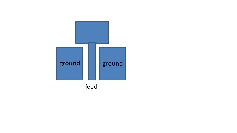
Please find the topology of the cpw which I need to model.
regards
Hi Iyami
Thanks,
Its a 3D model.
Yes, the design is symmetric, in that case how to implement that
Suppose I wan't to consider ground at right side of feed then I should cut the structure from the middle of the feed and consider half portion upto right side ground.
What should I do at the left side of the feed , Should I define the boundary like PML
I have never implemented that can you elaborate it little bit.
regards
Hi Iyami
Thanks, I guess I have to do some implementation to see where I get the best result.
Suppose I have two source as you suggested (option-3), then how I compute S11.
That is how I should use two sampled voltages and two sample currents at resistors of each source.
I have seen in literature some authors have used this, but I am not getting how to use two sampled voltages and current to compute S11 of the structure.
If you can explain me this I guess I can solve my problem
regards