rameshiloveu
Junior Member level 1

- Joined
- Sep 6, 2013
- Messages
- 19
- Helped
- 1
- Reputation
- 2
- Reaction score
- 1
- Trophy points
- 3
- Activity points
- 151
Hi,
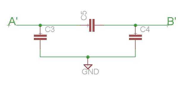
There are two scenario, which has higher coupling capacitance and higher actual capacitance between A and B ? and why ?
a> Metal A and Metal B
b> Metal A, Metal C and Metal B
Spacing between Metal A and Metal B in both cases is same.
Please help")
There are two scenario, which has higher coupling capacitance and higher actual capacitance between A and B ? and why ?
a> Metal A and Metal B
b> Metal A, Metal C and Metal B
Spacing between Metal A and Metal B in both cases is same.
Please help