Continue to Site

Welcome to EDAboard.com

Welcome to our site! EDAboard.com is an international Electronics Discussion Forum focused on EDA software, circuits, schematics, books, theory, papers, asic, pld, 8051, DSP, Network, RF, Analog Design, PCB, Service Manuals... and a whole lot more! To participate you need to register. Registration is free. Click here to register now.

[SOLVED] Coupling between Primary and Secondary windings in transformers?

Status
Not open for further replies.

righteous

Full Member level 2
Joined
Nov 29, 2017
Messages
130
Helped
0
Reputation
0
Reaction score
0
Trophy points
16
Activity points
1,282
Gents,

The question is; why do a load on the secondary winding result in increased current in the primary winding on some transformers? (or maybe all, I don't know.)

I have this question, because as I have been taught, the only coupling between primary and secondary is the flux in the core, and it is the primary that determines the amount of flux. At least this is how it is presented in textbooks :
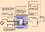
Screenshot from 2018-03-30 17-57-15.png

So if the only coupling is flux, is the increased current in the primary due to a badly designed transformer with mutual induction? Or are there another feedback (sec -> pri) mechanism in a transformer?

- - - Updated - - -

Never mind, I found some sort of answer here:

http://electronics.stackexchange.com/questions/169129/flux-in-transformers
 

why do a load on the secondary winding result in increased current in the primary winding

This was not addressed in the above link, but what really happens is that an ideal transformer acts like a power coupler, I mean, as the load increases (in the sense of delivered power),the secondary current increases and the currrent on primary increases accordingly, so, once the ideal transformer do not create or loose energy, it have to deliver a power to secondary equal to the power on the primary. Considering the ideal transformer, the ratio Vs/Vp will stay constant, therefore:

Power = V.I

Powerbefore = Vp.Ip = Vs.Is

Powerafter = Vp.(Ip↑) = Vs.(Is↑)

So if the only coupling is flux, is the increased current in the primary due to a badly designed transformer with mutual induction?

Every reasonably decent transformer design has a very small mutual inductance, and even the largest it may be, it is always negligible if compared to the self inductance value of each winding. If the transformer is purposely poorly designed with very few turns in each arm of the core, in this case you will really see a greater contribution of the mutual inductance effect, so this is why we have to select a number of turns as large as possible, so that magnetic field lies within the linear region of the BxH curve.

But when you refer to a "bad design", this is usually related to the undersize of the core cross-section area whithin where the magnetic flux travels, because if there is saturation (e.g more turns of the windings than allowed), a significant part of the power will be lost in the form of dissipated heat.
 

Power = V.I

Powerbefore = Vp.Ip = Vs.Is

Powerafter = Vp.(Ip↑) = Vs.(Is↑)

So what you are basically saying is Is↑ -> Ip↑ ?

I was actually looking for an explanation as to why it does that, the closest I have found is

the core magnetic flux is maximum under no load conditions and falls a little bit as the secondary is loaded. The ampere turns of the secondary due to the load are cancelled by the ampere turns increase on the primary due to that secondary load.

I found it in this thread https://electronics.stackexchange.c...y-transformer-winding-output-too-much-current

But I'm not exactly sure what it means in practical terms? could you say that "The inductance in the primary changes when load is applied on secondary"?
 

The way I think of it is this:

The primary is a coil of wire around a core. The only the thing that stops current from 'shorting' through it is the primary inductance (an ideal transformer would have infinite primary inductance).

This primary inductance operates like a regular old inductor, creating a certain amount of flux that the core needs to absorb without saturating.

If current suddenly flows through the secondary it creates 'new flux' and the direction of this flux 'cancels out' the inductance of the primary. So with less primary inductance primary current increases and it increases until it has completely cancelled out the 'new flux' from the secondary.

The transformer has now reached a new steady state where load current on the secondary has induced additional current in the primary as expected. Both the primary and secondary have more current and are 'generating' more flux but most of it cancels. The 'net flux' remains the same as if the secondary wasn't there.
 
But I'm not exactly sure what it means in practical terms? could you say that "The inductance in the primary changes when load is applied on secondary"?

Under normal conditions there is no change at the inductance value whether the load increase or not; either the self inductance or mutual inductance are not dependent on the magnetic flux.

the core magnetic flux is maximum under no load conditions

This makes no sense, the magnetic flux is directly proportional to the loop of current flowing through the core winding, so that an increase in current in any arm would increase the magnetic flux on the other side.
 

Hi,
the core magnetic flux is maximum under no load conditions
I agree with this statement.

If one calculates I_prim x n_prim - I_sek x n_sek (because both windings are on the same core).
One should be able to verify the above statement.

I've never done this before. The problem is that with a ready to buy transformer you don't know the winding count.
Maybe the core and winding loss has additional influence.

Klaus
 

If current suddenly flows through the secondary it creates 'new flux' and the direction of this flux 'cancels out' the inductance of the primary.

Yes, but why is the secondary flux opposing the primary, why couldn't it have the same direction? Is it for the same reason a solenoid shoots out the hammer in one direction even if it's powered by AC? I.e. the coil doesn't care about flux direction, it's always looking for the lowest inductance?
 

Hi,

Yes, but why is the secondary flux opposing the primary, why couldn't it have the same direction?
Indeed it does.

The primary winding is seen as current (power) sink, thus usually the current vector goes into the coil.
The secondary is seen as current (power) source, thus the vector goes out of the coil.

If you see both as equal coils you should use equal vector direction, then they will add.

In any case if you take care of (current_vector_direction x current_value_sign) then it's always correct.

Klaus
 

Hi,


Indeed it does.

The primary winding is seen as current (power) sink, thus usually the current vector goes into the coil.
The secondary is seen as current (power) source, thus the vector goes out of the coil.

If you see both as equal coils you should use equal vector direction, then they will add.

In any case if you take care of (current_vector_direction x current_value_sign) then it's always correct.

Klaus

Yes, adding makes sense, it has to increase current -> increased flux
 

Yes, adding makes sense, it has to increase current -> increased flux
Transformer's magnetic flux stays constant, regardless of the load. In other words, transformer's magnetic flux is the same with NO load, with 50% load, or with xx% load.
 

Yes, but why is the secondary flux opposing the primary, why couldn't it have the same direction? Is it for the same reason a solenoid shoots out the hammer in one direction even if it's powered by AC? I.e. the coil doesn't care about flux direction, it's always looking for the lowest inductance?

Well the thing to remember is that the secondary voltage is caused by the primary. So its polarity and thus the polarity of the load current therefore isn't an 'accident' so to speak.

From primary to secondary I think of it like this (where ' is prime meaning a constant rate of change):
Voltage -> current' -> flux' -> Secondary Voltage

With a resistive load, current will always 'oppose' the primary and cause it to draw more current. However reactive or active loads that store energy could in-fact 'increase' the primary inductance or start delivering energy in reverse (a transformer is completely bidirectional of course).


"the core magnetic flux is maximum under no load conditions"

In theory it's the same regardless of load.
 

Hi,

Transformer's magnetic flux stays constant, regardless of the load. In other words, transformer's magnetic flux is the same with NO load, with 50% load, or with xx% load.

true for an ideal transformer
...without winding loss.

But if you take winding loss into account then the flux will be reduced.

You may simply check this:
Use a small - short circuit proof - transformer with two independent (no electrical connection) secondary windings.
Now connect a stable AC voltage at the primary winding.

Measure the voltage of one secondary output (A) and note the voltage.
Now short circuit the other secondary winding (B).
and measure again the voltage of the first secondary winding (A). Now the voltage is reduced...indicating reduced flux in the core.

Klaus
 
That’s true though it doesn’t take uncoupled leakage flux into account. Presumably at some point that could dominate and saturate the core.
 

Transformer's magnetic flux stays constant, regardless of the load. In other words, transformer's magnetic flux is the same with NO load, with 50% load, or with xx% load.

true for an ideal transformer
...without winding loss

I presume we're talking about different phenomens or we are referring them by different nomeclatures. With no external amperian sources carrying electric currents around the arm of transformer core, there is no magnetic flux. The magnetic flux, for a given geometry is directly proportional to the electric current. By using the 4th Maxwell equation, the magnetic flux is derived by integrating the magnetic field B (which depends only on the current i, the meterial permeability μ along the electric current path) with the area encircled by the electric current, so the magnetic flux Φ is calculated by multiplying the magnetic field with the sectional area, therefore the magnetic flux do varies according the change in load, therefore the above statement seems incorrect - even would be not true with a permanent magnet inside the core arm (e.g analog meters with needle), once the load on secundary is dissipative.
 

Andre, the fluxes cancel.

I agree in some ways thats not intuitive but consider this:

The saturation current of a transformer is typically a tiny fraction of its allowed primary current under load. What I mean is that if you consider the magnetizing inductance and the allowed volt-seconds you can calculate the maximum magnetizing current that saturates the core. By design magnetizing current is usually <<10% of load current. So that tells you how much 'net flux' and current actually saturates the core.

The fact that transformers actually operate with well more than that peak magnetizing current flowing through them without saturating indicates that yes, the fluxes of the primary and secondary are in-fact cancelling to keep the net core flux below that small calculated value.
 

therefore the magnetic flux do varies according the change in load, therefore the above statement seems incorrect - even would be not true with a permanent magnet inside the core arm (e.g analog meters with needle), once the load on secundary is dissipative.
Incorrect.
There are 2 currents in a xformer. Magnetizing and the current that gets transferred to the secondary, just like an ideal xformer does.

Primary Current=Magnetizing + current that gets transferred.

While current that gets transferred is increased when there is load in the secondary (and hence, the primary current is increased), the Magnetizing stays constant (assuming no leakage and no winding resistance). The magnetizing is the one that gives the flux in the core, and is created as you have stated in the first part of your explanation.

People use the primary current as the one that provides the magnetic flux... they see that it has increased by adding load, and they say , the flux has increased also !

true for an ideal transformer
...without winding loss.
I perfectly agree with you and your post, but I wanted to keep it simple and by the way, to keep the worst case scenario, which is how the xformer is designed.
Notice that the OP in post #9 thought the flux is increased... where in practice is decreased, as you well explained. I believe that under no extreme conditions (like short circuit), the assumption of constant magnetic flux is better than a good approximation.
 

Okay, that somehow makes sense; even with no load on the secondary, there is still the voltage source on the primary energizing the input of the transformer. I was just considering the mathematical formulation of the magnetic flux, without taking into account the parasitic effects present on the non-ideal transformer.
 

Status
Not open for further replies.

Similar threads

Part and Inventory Search

Welcome to EDABoard.com

Sponsor

Back
Top