Continue to Site

Welcome to EDAboard.com

Welcome to our site! EDAboard.com is an international Electronics Discussion Forum focused on EDA software, circuits, schematics, books, theory, papers, asic, pld, 8051, DSP, Network, RF, Analog Design, PCB, Service Manuals... and a whole lot more! To participate you need to register. Registration is free. Click here to register now.

Coupled LC circuits - contradictory equations

Status
Not open for further replies.

htg

Full Member level 5
Joined
May 1, 2010
Messages
248
Helped
5
Reputation
10
Reaction score
3
Trophy points
1,298
Location
Poland
Activity points
2,862
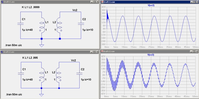
I consider two identical LC circuits, inductively coupled with the coupling coefficient k=1. Let y1 be the charge on the capacitor of the first circuit, y2 - charge on the capacitor of the second circuit. Let y1(0) = q > 0, y2(0) = 0. The equations that I get are y1'' + y2'' + ω^2 * y1 =0, y1'' + y2'' + ω^2 * y2 =0, where ω^2 = 1/(LC).
I subtract the second equation from the first and I obtain ω^2 * (y1-y2)=0, which contradicts the initial conditions y1(0)=q>0, y2(0)=0.
I do not understand why this problem appears and what to do.
 

k=1 means both inductances respectively both capacitors are connected in parallel with zero impedance inbetween. It's physically
impossible to have different voltage at the capacitors in this case, your assumed initial conditions can't exist, all calculations based on
it are meaningless.
 

    htg

    Points: 2
    Helpful Answer Positive Rating
LC circuits are INDUCTIVELY coupled, so my initial conditions are clearly possible.
 

I don't think so. In my opinion, it's similar to a problem previously discussed at edaboard: shorting two capacitors with a zero impedance switch.
 

    htg

    Points: 2
    Helpful Answer Positive Rating
It's the "same" behavior when you connect two caps in parallel with differents voltages.


Solve with k<>1 and see what happen when k->1.
The solution is the sum of two sinewaves, one of w = 1/sqrt(LC) and other of w->infinity.

In real cases, the second sinewaves vanish quickly because you always have losses.
 

    htg

    Points: 2
    Helpful Answer Positive Rating
No. You have inductance which prevents appearance of any much higher frequency components. It may be similar to connecting two capacitors by means of an inductive connector.
 

Perhaps you "see" the obvious facts from an equivalent circuit:

52_1273342750.gif
 

    htg

    Points: 2
    Helpful Answer Positive Rating
Please, just solve with k<>1 and see what happen when k is close to 1
 

    htg

    Points: 2
    Helpful Answer Positive Rating
Perhaps you are right. The inductance gets cancelled, because the secondary coil is initially shorted by the uncharged capacitor. So what happens, say, for k=.99?
 

Including the coupling coefficient k in the equations

y1'' + k*y2'' + ω^2 * y1 =0
k*y1'' + y2'' + ω^2 * y2 =0


Adding and substracting both equations

(1+k)*(y1+y2)'' + ω^2 *(y1+y2) = (1+k)*U1'' + ω^2 *U1 = 0
(1-k)*(y1-y2)'' + ω^2 *(y1-y2) = (1-k)*U2'' + ω^2 *U2 = 0


Then, the solutions are trivials.

U1 = y1+y2 : general sinewave of frequency w/sqrt(1+k)
U2 = y1-y2 : general sinewave of frequency w/sqrt(1-k)

--> y1 = (U1+U2)/2 and y2 = (U1-U2)/2

Is easy to see what when k-->1 or k-->-1 , one natural frequency -->w/sqrt(2) and the other goes to infinity.


In real circuits, the high frequency vanish as k goes close to +/-1 due the losses.

The image is a simulation with 0.1 ohm of windings resistance for k = 0.995 and k=0.9999

53_1273347695.jpg


At k=+/-1 with no losses you have a singularity: Infinite current at infinite frequency.
 

    htg

    Points: 2
    Helpful Answer Positive Rating
Hi Eduardo,

I have a different opinion on the contradiction showed:

In fact you have analyzed the circuit in frequency domain, These one approach is usable only in stady state condition (sinusoidal in this case) then without initial condition.

Initial condition are usable only in transient analisys.

For me the contradiction don't exist.

Ninux
 

In fact you have analyzed the circuit in frequency domain
He didn't. Look sharp, it's the differential equation solution in time domain.
 

Hi experts,

Has Anybody done some work on coupled resonators modelling in MATLAB. Any example would be might helpful for me. Thanks!!! Waiting for your reply.
 

Status
Not open for further replies.

Part and Inventory Search

Welcome to EDABoard.com

Sponsor

Back
Top