Continue to Site

Welcome to EDAboard.com

Welcome to our site! EDAboard.com is an international Electronics Discussion Forum focused on EDA software, circuits, schematics, books, theory, papers, asic, pld, 8051, DSP, Network, RF, Analog Design, PCB, Service Manuals... and a whole lot more! To participate you need to register. Registration is free. Click here to register now.

counter and 7-segment decoder problem

Status
Not open for further replies.

muttu.sarve

Junior Member level 2
Joined
Sep 30, 2011
Messages
20
Helped
0
Reputation
0
Reaction score
0
Trophy points
1,281
Activity points
1,465
HI every one,
I'm new to pic programming and i'm working on a project. i'm planning to use pic16f877.and please suggest me which oscillator i can use in this project.
the project is go like this...the project consist of 4*4 keyboard, 5 output LEDS, 8 digital outputs to drive another circuit, seven (7) digit 7-segment
display, 1 sesor input which will get a signal from sensor. which is used to find out motor rotation. the sensor is connected to 24v ac motor(1400rpm).
As the shaft of the motor rotate once then the sensor work once. the sesor input is taken as counter and which will be dispay in the 4 digit 7-segment.
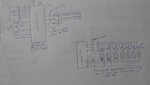
as pic16f877 has 32 I/O pins so i need to use 7-segment decoder in this project. the problem is..
1. i want to know the circuit diagram for 7-segment decoder with sample code for this project.
2. when the motor rotates with full speed then within 4second shaft will rotate 100 times so i'm dont know how to program for this. mean while my sensor is working as
counter and i need to display the same count in 7 segment display. so please help me.. its urgent.


thanking you..
 

Hello!

1. The circuit for wiring a 7-seg display and a micro controller must exist in thousands of versions on the net.
Now how many digits do you have to manage?
As for the source code, you don't need any. The best for you would be to understand what you are doing
and why you are doing it.
- Learn what a port is
- Learn what a LED is, how it works, etc
- Wire a single LED to your PIC, try to write a tiny program to blink it.
- Write another program to blink 2 leds independently to make sure you got it.
- Wire your 7-seg display (1 digit first). Try to blink all the segments independently.
- For any number, make a summary of the segments you have to blink (i.e. for 0,
you'll have to blink abcdef, for 1 bc, for 2 abdeg, etc...
-> At that point you know how to display one number.
- Now try to display 2 numbers with 2 7-seg displays.
-> You may use 1 port per segment if you have enough pins (with 32 IO, it should just fit if you have nothing else)
-> you may use 1 common port for data for all the displays and multiplex their common pins...
In this case, you need 7 I/O pins for the sets and 4 I/O for the enable signals.
- Upgrade for the number of 7-seg units you want to use

2. For your motor, since the rotation is very slow compared to the processor clock, you should
use a timer. The time between 2 pulses of your sensor (1 per rotation) will be 4/100 or 1/25,
which means 40 ms. If the timer runs at, say, 20 MHz, then you will get 20 000 000 / 25
clocks, therefore 800 000 clocks. This gives you a quite good accuracy. After that, you know that
800 000 clocks corresponds to 1500 rpm, and therefore it's easy to calculate speed from
the timer value.

Dora.
 

thank you for replying..
1. i'm using 7 display devices of 7-segment displays. i worked up to three 7-segment display in previous project. For operate seven 7-segment display in this project i need 7 i/o lines for segments (a,b,c,d,e,f,g) and 7 i/o pins to connect common cathode pin. so totally it required 14 i/o pins. but i'm facing shortage of i/o pins, so i need to reduce these pins using decoder or something easy circuit. so please let me know how can i reduce these pins as much as possible. please can explain it with simple code n diagram. i tried many ways but i didnt get any positive response.

2. can u please tell the simple code for timer using 16f877 with 20MHz for 144rpm motor..

thank you so much :)
 

Hello!

If you want to further reduce the number of pins:
As you use 7 common cathode signals, you may reduce further with an external decoder
(e.g 74HC138). Therefore you will reduce the number of pins to 3. And the good thing is that
as there are 8 outputs, you can use the 8th output unconnected to unselect the display
and therefore not use the enable signals. For example: 000 selects digit 0, ... 110 selects
digit 6 and 111 selects nothing.

As for the sample code, you can find a lot on the net, especially for PIC. But one thing is
sure: you will never find the code for your particular case: 16f877, 20MHz, 144 rpm.
And another thing is also sure: nobody will write it for you, at least not for free.
Write your own code, and if something does not work, describe accurately what does not
work, and publish the piece of code where the problem arises. Probably somebody will
understand your problem at once and give you advice.

Dora.
 

thank you for your precious time.. i understood the concept but it is very helpful if u explain how to connect pic16f877 with 74HC138, can u provide me a circuit for it.. as i'm using common cathode 7-segment display i need to connect all the cathode pins to pic so it needs 7 i/o pins for that.. how do i drive individual display without connecting cathode pins to pic micro controller? please let me know if you have circuit for this.. if i'm not wrong i need to convert my hexa number to BCD number in my program if i use BCD to 7-segment decoder right.. and i no need to convert hexa to decimal number.. right? can u elaborate your example that you use to explain above.. please provide the connection details for interfacing pic16f877 to 74HC138.
 

Hello!

74 HC 138 is a decoder.
Basically, you have 3 inputs and 8 output.
Here is its table:
input | output
i1, i2,i3 | o0, o1, o2, o3, o4, o5, o6, o7
--------------------------
000 | 11111110
001 | 11111101
etc... | ...
110 | 10111111
111 | 01111111

Note the inverted outputs if I remember correctly.
This means that if you set 000, the only the output 0 will be low, all the others will be high.
Set the common cathode to output, and I guess it will work.
Now you are telling me that use a BCD to 7 segment? I thought you were driving the LEDs directly from a port.
Of course, if you use a BCD to 7 segment chip (i.e. 74 HC 42 or HC47, I don't remember), then you can save 3
more bits and you can drive the whole stuff with a single port (4 bits for data, and 3 for select).
The documentations of 74138 and 7447 are on the net. (all the 74 series, anyway).

Dora.
 

i have attached block diagram with this and please go through it and do help me to solve this issue.. and also let me know the algorithm for code to achieve this display problem..


thank you :)
 

Attachments

  • Picture 018.JPG
    Picture 018.JPG
    528.6 KB · Views: 98

Status
Not open for further replies.

Part and Inventory Search

Welcome to EDABoard.com

Sponsor

Back
Top