Continue to Site

Welcome to EDAboard.com

Welcome to our site! EDAboard.com is an international Electronics Discussion Forum focused on EDA software, circuits, schematics, books, theory, papers, asic, pld, 8051, DSP, Network, RF, Analog Design, PCB, Service Manuals... and a whole lot more! To participate you need to register. Registration is free. Click here to register now.

Core loss in Alloy powder core sounds too low?

Status
Not open for further replies.

cupoftea

Advanced Member level 5
Joined
Jun 13, 2021
Messages
2,609
Helped
54
Reputation
108
Reaction score
115
Trophy points
63
Activity points
13,681
Hi,

We are doing Boost PFC.
115VAC, 120khz = fsw, 270W = Pout, 390Vout
Inductor is 60 turns of ECW round a micrometals HF130125-2 core. (460uH at zero Amps)

HF130125-2 core (Page 57)
https://www.micrometals.com/design-and-applications/literature/

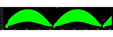
As you can see, there as a large amount of inductor ripple current at the peak of the mains. dI = 4.1Apkpk and dB = 0.293T (pkpk)
However, the core loss calculation from page 31 of the above Micrometals catalog gives only 137mW of core loss. (and thats an abs max, since as you know, the Bpkpk gets less as one moves away from the mains peak)

Doesn’t this sound just way , way too low?
 

Attachments

  • PFC inductor current.jpg
    PFC inductor current.jpg
    87.7 KB · Views: 115

The method of calculating core losses as in the attached excel concurs very well with the "Inductor anlyzer" method on the micrometals website.

So....the method is......
1...use their relation for ur vs H to get the ur value at each current step from say 0.1A to 10A say....stepping up by say 0.1A at a time
2....Then calc the H and dH for each step
3....then calc dB from dB = uo.ur.dH
4...then accumulate the dB into the running B total.

...thats it.

The above concurs very closely with micrometals website calculator.
Would you agree with this method?

_---___--___--___--__
__---___-____---______
and - what are the results for a design with +/- 20% ripple at peak mains .... ?
The "inductor analyzer" on micrometals website gives the following results.....which concur well with the above "dH stepping" method.. This is for 35% ripple...ie, the di at mains peak is 2.4A and the (average) mains peak current is 6.8A.

So
core loss = 1.5W
winding loss = 2W

This is for torroid MS-106160-2
(a) two stacked torroids
(b)...34 turns of AWG20
PFC with 115vac input, 550w output, 120khz, vout = 220vdc
 

Attachments

  • PFC L calxc __MS_106160_2_ _fromu.zip
    281 KB · Views: 71
Last edited:

Status
Not open for further replies.

Similar threads

Part and Inventory Search

Welcome to EDABoard.com

Sponsor

Back
Top