Continue to Site

Welcome to EDAboard.com

Welcome to our site! EDAboard.com is an international Electronics Discussion Forum focused on EDA software, circuits, schematics, books, theory, papers, asic, pld, 8051, DSP, Network, RF, Analog Design, PCB, Service Manuals... and a whole lot more! To participate you need to register. Registration is free. Click here to register now.

Converting sine wave to square

Status
Not open for further replies.

andrea_mori

Member level 2
Member level 2
Joined
Aug 14, 2012
Messages
44
Helped
0
Reputation
0
Reaction score
0
Trophy points
1,286
Visit site
Activity points
1,727
I'm using the following circuit to convert sine wave to square, but it does not work. Instead of a square wave I get a sawtooth wave.
Simulating the circuit I get the right square wave.
The circuit was taken from Wenzel library at **broken link removed** SQUARER.JPGOut.jpg

Anyone has any idea?
 

Response also depends on operating frequency. Try increasing value of C1. Put a bypass capacitor on supply line. Further increase value of R17.
 

The operating frequency is 11.2896MHz.
Already tried to increase C1 to 100nF, no change.
Already added 1uF film cap on power supply, no change.
Already increased or decreased C29 from 1nF to 100nF, no change.
The strange thing is that the sawtooth output waveform does not reach 0V, it swings from around 3 to 6V.
I'll try to increase R17.
Any other idea?
 

Its a Schmitt Trigger circuit. Can you increase the gain of the transistors?
 

Heya Andrea - what is the output impedance/amplitude of your sinusoidal source?

Triangular edges (implying slew rate limitations) and not getting full (i.e down to zero) output amplitude suggests to me that the transistors aren't being driven hard enough - especially given the ~30 mA peak collector current set by R14. This configuration is a differential amplifier, amplifying the difference between the (fixed) voltage at the base of T4 (on the right) and the AC voltage superimposed on the base bias of T5. The dynamic (AC) base current of T5 is likely to be significant here which will load your source - if it can't maintain a respectable amplitude (~ +/- a few 100 mV) at the base of T5 you might observe the problem you describe.

You *might* (I'm shooting from the hip here) squeak a little more performance out of the amplifier without changing the active devices by decreasing the current (increasing R14) and correspondingly increasing R17. The Miller capacitance of T4 will set a limit to how far you can go though.

I previously uploaded a sketch in post #6 of this thread (https://www.edaboard.com/threads/279340/) that might be an easier way forward for you... good luck!
 

Thanks all.

The source is a 2 transistors Butler oscillator buffered by an emitter follower with 330R emitter resistor. The output amplitude of the emitter follower is around 4V p-p.
I will try to decrease the current in the squarer.

Thank for the link, BTW I would prefer to use discrete squarer rather than gates or comparators.
 

I tried decreasing the current in the differential, but unfortunately nothing changed.

Now R14 is 475R and R17 is 1K2, so around 5mA total.
The source should drive easily the differential.

Any other idea?
 

Insisting on using discrete transistors is going to make things more difficult...

If you're getting a triangular output, then it sounds like a problem with capacitive loading on the output. Make sure there's no significant stray capacitance on that node (10pF at most). Increasing the bias current in the pair and decreasing R17 should also help somewhat. Using a current mirror load would also help. You might try getting a monolithic transistor array, like the kind RCA used to make.
 

I think the most important point here is how does andrea_mori know the waveform isn't square?

What is being used to check the wave shape and what loading effect does it have on the signal?

Brian.
 

To check the wave shape I'm using the probe of my Rigol DS1102E directly on R17 terminal. No coupling capacitor. I do not think it's strongly loading the squarer.
I'll post the waveform from my scope.

I'm testing all the circuit, oscillator, buffer and squarer, on the breadboard.
 

That's OK. Sorry for asking but I had to be sure you weren't using a low bandwidth scope. I used to get students complaining they didn't see nice straight edges on computer busses like the text books show and always had to explain about rise and fall times to them.

Brian.
 

I know I don't own a Le Croy or a Tek, but the chinese Rigol is able to measure 12MHz.

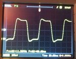
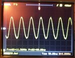
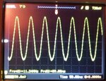
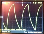
Follows some images from my scope:
- XO is the square waveform from a 3 USD canned XO
- Butler: is the sine wave from the crystal oscillator
- Buffer: is the sine wave from the oscillator buffer
- Squarer: is the bad waveform from the differential convertor

All measurement was done DC coupled and 10X probe.

XO.jpgButler.jpgBuffer.jpgSquarer.jpg
 

Thanks for the images, but I'm sitting here squinting at them and can't quite make out the text on the screen - what's the DC offset and volts/division on the buffer waveform? Is that 50mV/division?
 

Status
Not open for further replies.

Part and Inventory Search

Welcome to EDABoard.com

Sponsor

Back
Top