Continue to Site

Welcome to EDAboard.com

Welcome to our site! EDAboard.com is an international Electronics Discussion Forum focused on EDA software, circuits, schematics, books, theory, papers, asic, pld, 8051, DSP, Network, RF, Analog Design, PCB, Service Manuals... and a whole lot more! To participate you need to register. Registration is free. Click here to register now.

[SOLVED] Converting Shunt S-parameters into Series

Status
Not open for further replies.

ferdinnand

Junior Member level 3
Joined
Oct 12, 2010
Messages
30
Helped
2
Reputation
4
Reaction score
2
Trophy points
1,288
Activity points
1,525
Hi all,

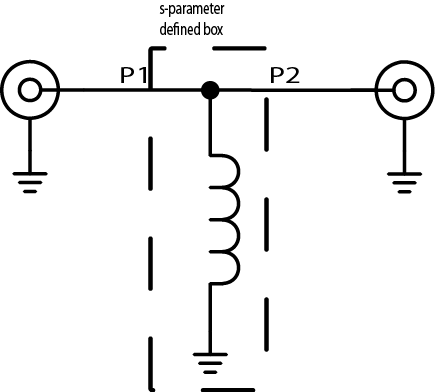
As easy as it may seem, I am having trouble trying to convert S-parameters of a two-port network between two basic configurations which I believe should be a trivial operation. I have been provided the S-parameters of a passive two-port device (an RF choke coil to be precise) which is measured in the shunt configuration like so;

**broken link removed**

I am therefore needing to retrieve its series S-parameters using the data from this shunt measurement. However, I have so far failed to do so and most probably I have been missing out something very essential. Could anyone help me achieve the S-parameters in series configuration?


PS: Things I have tried so far; manipulating-transposing ABCD matrix of the data in order to convert sigma network into pi network, assigning Y-parameters of the initial data as in its new Z-parameters but none has worked properly. The shunt S-parameters of the coil can be found at the following link in case you would like to take a look at; https://www.coilcraft.com/zip/4310lc.zip
 

You don't need to convert s-parameters because they have been especially measured being as parallel configuration to insert these "RF choke coils" onto circuit diagram.
So, Port-1 and Port-2 are your inut and output ports and this coil has already been grounded (because it's connected to Vdd).All you should do is to insert a black box who will represent these s-parameters onto your schematic being as series.
Like this..
2846359500_1374208936.png
 

It is rather clear why it's been measured with a short to the ground, as this particular configuration fits most of the applications. The problem is though, I won't be using it in its conventional configuration. Rather than decoupling the DC, I will be using it as a bias tee replacement and will be running all the supply current through the coil to my output node. So consequently, I need to have its S-parameter definition in series.
 

For using the inductor as a serial component can the impedance be calculated from data sheet S11 which is the parallel result of inductor and system impedance. System impedance is 50 Ohm, according to the s2p file.
But in this case is it something that not seems to be correct as the coil have negative resistance.
From by Coiltronics provided S11-parameters for 4310LC-352L, a 3.5 uH coil:
coilt339.png
S11. Resistive peak 67 Ohm.
Whatever reactance the shunt coil have, can it not increase total measured resistive part above 50 Ohm if system impedance is 50 Ohm. 67 Ohm is a bit high as result for an resistance in parallel with 50 Ohm.
Maybe problem with instrumentation calibration, but problems starts at 50 MHz which not is that hard to measure with reasonable good precision.
 
Last edited:
Maybe problem with instrumentation calibration, but problems starts at 50 MHz which not is that hard to measure with reasonable good precision.
It's not clear to me where you see negative resistance at low frequencies in the S parameter table. S11 must be restricted to the left half plane for positive real impedances of the shunt element. This is the case up to the GHz range. Above, there's obviously a calibration/de-embedding problem.

The given S-parameters may be still inplausible at low frequencies, I didn't check that in detail.

It should be noticed, that the 11 mm length of the 4310LC doesn't allow an exact de-embedding as lumped component in GHz range. I would also doubt that a shunt S-parameter measurement is meaningful without referring to a specific application circuit geometry.

Secondly I don't understand why a bias-T should use a series configuration.

- - - Updated - - -

O.K., I see. Not the full left half-plane is allowed, only a part of it.

- - - Updated - - -

However, if you calculate the shunt impedance from the table values, you get a positive real part up to 1.7 GHz.

Code:
Z = Z0*(s11+1)/(-2 s11)
 

Attachments

  • s11_352.zip
    18.8 KB · Views: 62
Last edited:
if u are using the inductor as a bias network, with a large capacitor to ground where u drew the grounding symbol, the u are still essentially using the inductor in shunt. So u are probably still good to go.

You chose to measure the inductor in a two port test fixture, with a 50 ohm load in parallel with the inductor. You must realize that that will cause some measurement uncertainty. What I would do is curve match the S21 data to the inductor modeled as a L and Ql. When I had the lumped element equivalent values fo rthe inductor approximated, I would just use those in my circuit design. IF there were any weird glitches in the S21 data at higher frequencies.....I would pick a better (smaller physically and value wise) inductor!
 
Thank you all for your responses, it is now clear there are numerous problems concerning even the reliability of the measurement, as well as the performance of the coil itself and its representation. I have decided not to bother using it anymore and replaced it with a λ/4 stripline to prevent possible injection of my RF input going through the caps in the bias network.


This is the case up to the GHz range. Above, there's obviously a calibration/de-embedding problem.
Indeed, there seems a rather huge problem probably during the de-embedding operation. I had thought it was me handling it all wrong when I saw negative impedance values after my conversion as well.


It should be noticed, that the 11 mm length of the 4310LC doesn't allow an exact de-embedding as lumped component in GHz range. I would also doubt that a shunt S-parameter measurement is meaningful without referring to a specific application circuit geometry.
This I think is another huge problem jeopardising the reliability of the provided measurement data.


Secondly I don't understand why a bias-T should use a series configuration.
It is simply because I intended to use it as those inductors indicated below, but having rather long striplines connected to both ends of the coil. In which case there are no large caps nearby to ground it.


if u are using the inductor as a bias network, with a large capacitor to ground where u drew the grounding symbol, the u are still essentially using the inductor in shunt. So u are probably still good to go.
Unfortunately all my µF caps had to go further away from the coil and I had just little caps nearby as low as 10p, which is as well at the end of a long stripline. So who knows what impedance would the coil see when looking at those caps far away.


You chose to measure the inductor in a two port test fixture, with a 50 ohm load in parallel with the inductor. You must realize that that will cause some measurement uncertainty.
Now I am certainly not in favour of their measurement setup as well.


I would pick a better (smaller physically and value wise) inductor!
Definitely, I wouldn't recommend anyone using this coil in critical high frequency applications.
 

It is simply because I intended to use it as those inductors indicated below, but having rather long striplines connected to both ends of the coil. In which case there are no large caps nearby to ground it.
I see. But you'll need to model the striplines and the transmission line T to get a halfway meaningful results.

- - - Updated - - -

Definitely, I wouldn't recommend anyone using this coil in critical high frequency applications.
For high performance bias tees, one would preferably use pyramid coils. They aren't particular small but have the GHz active part concentrated at the tip.
 

I see. But you'll need to model the striplines and the transmission line T to get a halfway meaningful results.

- - - Updated - - -


For high performance bias tees, one would preferably use pyramid coils. They aren't particular small but have the GHz active part concentrated at the tip.

Yep, all the lines were already modelled, was just missing a data element of the coil to complete the whole thing. Pyramids would have been the best choice if size wasn't an issue, that's right. Anyway, turns out a simple quarter wavelength line has much more broadband capabilities than any coil I could have used.
 

It's not clear to me where you see negative resistance at low frequencies in the S parameter table.
No, I didn't see any negative resistance below 1700MHz, but the curve did look fishy above 50 MHz.
A bit fun thing, was still curious about Coilcraft S-parameters.
Did repeat same measurement for a similar ferrit coil and got a rather perfect curve. No circles around 50 Ohm as Coilcraft did got.
My fixture was however very simple, FR4 PCB and two short coax cables soldered directly on PCB.
Perhaps PCB material absorbed resonances so I did repeat same thing in air. No, it did still not looks like Coilcrafts curves.
Then I got the crazy idea to preset the VNA and not load any calibration correction before doing the measurement.
Bingo! Now I got almost identical curve as the one by Coilcraft. Curve did even go negative at same frequency, 1700 MHz.
Think they must have same VNA type as I have, to get such similar curves.

By Coilcraft provided PDF says:
The S-parameters of a sample was measured, and then the circuit board parasitics were
de-embedded using circuit simulation software.


Trustworthy text, but probably a lie, no signs of anything de-embedded.

This shows the problem with VNA's. Anyone can do measurements, the hard thing is to set up the instrument to get correct results.
 

Status
Not open for further replies.

Part and Inventory Search

Welcome to EDABoard.com

Sponsor

Back
Top