Continue to Site

Welcome to EDAboard.com

Welcome to our site! EDAboard.com is an international Electronics Discussion Forum focused on EDA software, circuits, schematics, books, theory, papers, asic, pld, 8051, DSP, Network, RF, Analog Design, PCB, Service Manuals... and a whole lot more! To participate you need to register. Registration is free. Click here to register now.

Convert tube relaxation oscillator circuit to modern circuit?

Status
Not open for further replies.

Michael Weaser

Member level 3
Joined
Aug 4, 2015
Messages
55
Helped
1
Reputation
2
Reaction score
1
Trophy points
1,288
Activity points
1,860
I am trying to have an old tube based relaxation oscillator circuit converted to a modern circuit. This circuit has the ability to be controlled using a pitch pedal ( also a potentiometer ) and with 2 potentiometers . the potentiometer on the left of the pedal changes the range of the pedal , than the one on the right changes the grid bias of the tube which changes what the relaxation oscillator sounds like. I know how to make a relaxation oscillator circuit, but don't understand how the other components would be added to a modern relaxation oscillator circuit.
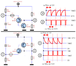
relaxation oscillator.png
 

If you want to make it with a single transistor, use either an UJT or a PUT.

 
@AudioguruThe bottom one seems the most similar to the original output , what about the 2 potentiometers and the pedal , how would they be connected?

This simulation is a programmable unijunction transistor resembling second schematic in AudioGuru's post #2.

Values were selected to operate in the audio range. One potentiometer adjusts frequency. That is your pedal.

More effort is needed to find where to put another potentiometer so you can alter the tonal quality.

programmable unijunc transis 3V supply 107Hz (pot adjust freq).png
 
This simulation is a programmable unijunction transistor resembling second schematic in AudioGuru's post #2.

Values were selected to operate in the audio range. One potentiometer adjusts frequency. That is your pedal.

More effort is needed to find where to put another potentiometer so you can alter the tonal quality.

View attachment 164284

@BradtheRad Technically the left potentiometer changes the range of the pitch pedal . So really I should be able to put another potentiometer in with the pitch pedal, like the original circuit to get the left potentiometer. The potentiometer to the right of the pedal is going to be a little bit more complicated , but though I was on another electronics forum and they gave me this RC circuit , without really explaining what it does , and was told this circuit would replace the other potentiometers.
thN2y[1].png
 

Hi,

From what I've used such circuit blocks for..., the diodes with their respective resistors create separate paths for charging and discharging the capacitor, and driving whatever is connected to 'out'.

A search for 'gate drive circuits' might help to understand the circuit block. Can be used for creating 'on' or 'off' delays, fast/slow turn-on and turn-off.
I also forgot to say , he told me the circuit is for attack and decay but that is all he told me.
 
Last edited:

Example of simple filter which changes an incoming waveform. The potentiometer was dialed from min to max resistance. (Slowly at first, then rapidly. Therefore a logarithmic taper makes for smoother adjusting as compared to a plain taper.)
Other filter configurations can be found to change the waveform in other ways.

100 Hz sq wave series cap pot adjust to gnd spikey output.png

--- Updated ---

Another simple circuit. Potentiometer selects a mix between two filters: a) high-pass CR and b) low-pass RC.

Potentiometer was dialed from left to right during simulation run.

pot select between RC vs CR filters 100 Hz sq wave.png
 
Last edited:

Thyristor is a combination of the words thyratron and transistor.

These devices have only two states: open (nonconducting) and triggered (conducting). No linear operation.

The two transistor circuits that AG provided emulate that function. The PUT that I suggested does too.

I guess that you could also use a sensitive gate SCR too, but the triggering characteristic may be a little sloppy compared to the suggested devices.
 

A more complex alternative could be a pair of
comparators and a SRFF, as comonly done in PWM
chips for the timing ramp. Upper comparator
sets FF, lower resets FF, FF output controls a
switched discharge current from the Q pin against
a fixed charge current applied to a timing cap,
and the voltage there wraps around to the window
comparators.

You can see the scheme in some older datasheets
for Unitrode / Silicon General PWMS, the 15/25/35xx
series voltage mode ones all use this scheme
(implemented in way fewer transistors than the
piece-parts scheme I describe)

Control the charging current and you have a CCO;
add a voltage-to-current-converter and you have
a sawtooth VCO. Or add a current mode DAC and
have a NCO.

Buffer the timing ramp with another A=1 op amp to
keep load from messing with frequency.
 

Status
Not open for further replies.

Similar threads

Part and Inventory Search

Welcome to EDABoard.com

Sponsor

Back
Top