Continue to Site

Welcome to EDAboard.com

Welcome to our site! EDAboard.com is an international Electronics Discussion Forum focused on EDA software, circuits, schematics, books, theory, papers, asic, pld, 8051, DSP, Network, RF, Analog Design, PCB, Service Manuals... and a whole lot more! To participate you need to register. Registration is free. Click here to register now.

[SOLVED] Convert resistance to current or voltage

Status
Not open for further replies.

matax

Newbie
Joined
Nov 11, 2021
Messages
3
Helped
0
Reputation
0
Reaction score
0
Trophy points
1
Activity points
25
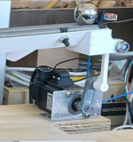
I have a reisistor made out of 2 resistance wires and they get connected by a moving metal ball. The resistance changes from 6 Ohms to 66 Ohms. I need to make a circuit to read voltage(0V-10V) or current(4mA-20mA). Right now I read it with a voltage divider but its nonlinear and I'm looking for suggestions to make it linear what circuit should I use. All suggestions are appretiated and thank you for your time.
 

Hi,

R = V / I ... or V * 1/I

V is above the fraction line, thus it´s proportional = linear to R
I is below the fraction line, thus it is multiplicative inverse = non linear to R

so the solution is to let "I" be constant and measure V.

--> use a constant current source.

A useful constant current maybe is 5mA ... 50mA (any other is possible)
so for 10mA you get rather low voltage.
I recommend to use an OPAMP to amplify this signal to your desired range.

For very high accuracy you should consider a 4-wire measurement technique (kelvin wiring)

Klaus
 
  • Like
Reactions: matax

    matax

    Points: 2
    Helpful Answer Positive Rating
I am looking at the constant current source circuits and I don't know which one would be the best for me. I have DC voltage that I can change from 24V to 5V.
 

Hi,

you are looking for the "best", but you don´t say in which regard it should be the "best".
There is no one and only "best" current source. (otherwise there was no reason to build different ones)

Often the problem is that that one did not decide the requirements ... or the target.
Deciding the requirements should be the first thing when building a device.

Currently we just know about a moving metal ball and the resistance range.
But we don´t know what make the resistance change, nor the environment. We don´t know whether you are interested in amplitude, phase angle, frequency, .... accuracy, precision ... how often you want to measure.
We don´t know whether you want a LED to become darker or brighter, or you want to use an analog measurement device, or maybe a microcontroller.
It could be simply switching a relay, or you could be a complex mathematical signal analysis.

The metal ball could be moving 1D, 2D, 3D .. or rotate in several ways...

****
Back to the current source: (from simple to more precise)
* It could be a simple resistor, mabe a PTC or NTC ... and thelinearity is good enough.
* One could by a current source IC.
* One could use a resistor transitor circuit,
* ...maybe add a zener.
* one could use a voltage regulator
* or an OPAMP circuit
* or an advanced OPAMP circuit with precision resistors and precision voltage reference.

We also don´t know about the power source. Is it mains powered, or do you need a low power battery operated device.

Klaus
 

    matax

    Points: 2
    Helpful Answer Positive Rating
This is the system. The resistance changes with the position of the ball. The power source is from a power suply. I need to regulate the ball to stay in the middle. Sorry the picture doesnt show everything its the only one I have right now.
 

Attachments

  • Untitled.png
    Untitled.png
    216.9 KB · Views: 100

If you really need a linear output, below is the LTspice simulation of a relatively simple circuit to give a linear voltage change with change in resistance:
The LM317 voltage regulator is configured to give a constant 50mA into the wire resistance (Rwire).
(The LM317 regulator maintains a constant 1.25V between OUT and ADJ so the current is 1.25V / R1)
U2 op amp amplifies the voltage from this current through the wire resistance by a gain of 3 to give an output of about 1V to 10V (yellow trace) for a wire resistance change of 6Ω to 66Ω (horizontal axis).

Will that work for your requirements?

1636666941709.png
 
  • Like
Reactions: matax

    matax

    Points: 2
    Helpful Answer Positive Rating
A possible problem of your rheostat sensor is that the possibly varying contact resistance of the ball adds to the measured resistance. An alternative usage of the resistance wire arrangement would use one wire as potentiometer and the other as wiper contact.
 
Status
Not open for further replies.

Similar threads

Part and Inventory Search

Welcome to EDABoard.com

Sponsor

Back
Top