Continue to Site

Welcome to EDAboard.com

Welcome to our site! EDAboard.com is an international Electronics Discussion Forum focused on EDA software, circuits, schematics, books, theory, papers, asic, pld, 8051, DSP, Network, RF, Analog Design, PCB, Service Manuals... and a whole lot more! To participate you need to register. Registration is free. Click here to register now.

[SOLVED] Controlling Mosfet (P-Channel)

Status
Not open for further replies.

miramark

Newbie level 3
Joined
May 4, 2011
Messages
3
Helped
0
Reputation
0
Reaction score
0
Trophy points
1,281
Activity points
1,321
Hi,

I`m facing some problems with controlling the two stage mosfet electronic key., as it should be.

48_1304529746.png


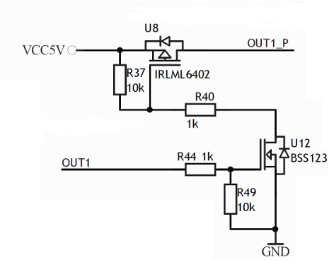
The Out1 input is swinging from 0 to 3,3 V (its uC pushpull output stage). The outp1_p is always between circa 3,3 V to 4,9 V (when loaded with two leds for testing witout resistor). At 3,3 V (near the close stage probably) there is a very little Id current here (about 0,3 mA). How can I fully close that transistor? For testing the R40 is removed and the place is soldered with tin.

Should I use another main P-Mosfet? I cannot rise the +5V. The voltages on the U8 gate is chainging from 0 to 4,4 V as the out1 input is pwm signal (about 50 kHz) so I think that there is no problem.

The main purpose of this thing is to control the led which is max 100-200 mA current with PWM signal 30-100 kHz would be nice. What will be the best resolution?

Best regards.
 

Sounds like you want the output at the led's to switch between zero and 4.9 V.

Your problem is the upper P-mosfet U8 won't turn off. RIght?

It turns on by grounding its gate through the bottom device U12.

U12 goes to low impedance when its gate receives a positive pulse. That's the idea.

You say you're getting zero V at the gate during a positive control pulse. Okay.

As a test -- can you try disconnecting everything at U8 gate except the R37 10k resistor? That would send 5V to the gate. Surely that will turn it off.

Verify 5V at the gate with a meter.

If it doesn't turn off then either it's defective or its operating characteristics have been changed such that it needs a higher positive voltage to turn it off.

Test to see if any current is going into the gate. You must connect a resistive load at the output for this test. If current can go into the gate then the gate was perforated ( likely by static electricity) and the mosfet is ruined.

As a further check you should also make sure whether current can come out of the gate through your voltmeter to ground.
 
Last edited:
I think you are having problems because you drive the mosfet with very low current and high switching speed,
change R40 to 50 ohm and R37 to 200 , this will give you a good enough switching speed.
R40 controls the turn on speed and R37 the turn off speed
If you can use 30k instead of 50k pwm frequency.

Alex
 
A 4.4V at gate of U8 will not enough to make it fully off. Look at the data sheet, VS - VG should be less than 0.4V to make sure that device is OFF.
BSS123 shuld able to produce a close voltage of around 5V at it drain. I am not sure why it is coming only 4.4V.
R40 has to be shorted, and you can try using a different FET for U8 with more VGS(threshold).
If you are using a capacitive load along with LED at output, this might also create problem for not letting the U8 to be fully off.
 
Thanks for a lot of answers.

BradtheRad:
I`ll try to disconnect everything from the gate leaving only the pullup and check is there some current flowing through the gate.


alexan_e:
As I said, I`ve removed the R40 1k resistor so there is plenty of current to turn-on the U8, but maybe there is not enough current to switch it off by the 10k resistor. I`ll try changing it. But changing the resistor to 50/200R I think that there will be to much current flowing by bss123. Its battery operated device, I must count every ten of miliamps:(. I`ve checked the characteristics on oscilloscope and they are very fine, maybe there is little rise falling time in the square wave, but for me its enough.

umesh49: Thank you for your post, I thought that it could be a problem and I think too, that the 4.4 V is something that should not happen at the drain of U12. I'll change the transistor(s) and check everything once again. Do you suggest to use U8 with HIGHER Vgs? I thought that lower Vgs is better, not higher. There is no capacitive load at output.

Miguel Gaspar: thats for simulation, thats what I want to achive, maybe with a higher switching speed ;).
 

Yes, battery operation would be a problem because the consumption would be about 50mA with the values I gave.
Your mosfet doesn't have a high gate capacitance so if the square wave looks good enough for your application then you can use high values.
The turn off speed is as important as the turn on speed, also check if you get a square wave for the lower/higher pwm duty cycle , I mean if you have 99% then the off pulse width for 50KHz will be 1%*20uS=200nS off time and the mosfet must be able to turn ff and on again in that time window.
I don't know if you can use a single Nmosfet as a low side switch (ground side) to the leds instead of the two mosfet high side switch.
I can't explain the 4.4v you get from U12, have you tried to connect the out1 to gnd to see if you get the same result?

Alex
 
umesh49: Thank you for your post, I thought that it could be a problem and I think too, that the 4.4 V is something that should not happen at the drain of U12. I'll change the transistor(s) and check everything once again. Do you suggest to use U8 with HIGHER Vgs? I thought that lower Vgs is better, not higher. There is no capacitive load at output.

More VGS would be better for your application as it can ensure the FET to be OFF even for the voltage around 4.5V at gate.
 
When the Nmosfet is off the gate voltage of Pmosfet should be 5v, I think that there is something "wrong" with the circuit that drives out1.
Have you measured if the voltage is actually 0v or more at the mcu output?
Another solution would be to use a NPN transistor in place of the Nmosfet but the consumption would be slightly higher because of the base-emitter current, about 1mA if you use a 3k3 base resistor.

Alex
 
Okey, now everything is ok.

Finally I`ve changed both transistors, R40 is 0R and R37 is 4k7. Before that I`ve tested the Ig current of U8 it was 0, next I`ve checked the driving of U8 after lifting the gate of U8 leaving it connected only to VCC5. Pulling down the gate of U8 there was 5V at drain, after leaving it open so gate is reaching 5V, the voltage at drain was ... 4,95V. Yesterday it was working but 3,3 to 4,9V ;]. Broken transistor, I`ve resoldered to new one, checked - it works as it should. Next BSS123, broken too! Cannot check the Ig because of the board design, but the voltage with soldered U12 at gate was about 1,7 V today after removing U12 it was 3V (after the divider 3,3 - > 3V) so -> broken bss123 too. Resoldered U12 and output swings from 0 to ideal 5V!

Thank you all guys. I think that this is what I needed.

Best Regards.
 

Status
Not open for further replies.

Similar threads

Part and Inventory Search

Welcome to EDABoard.com

Sponsor

Back
Top