Continue to Site

Welcome to EDAboard.com

Welcome to our site! EDAboard.com is an international Electronics Discussion Forum focused on EDA software, circuits, schematics, books, theory, papers, asic, pld, 8051, DSP, Network, RF, Analog Design, PCB, Service Manuals... and a whole lot more! To participate you need to register. Registration is free. Click here to register now.

[SOLVED] Controlling Inductor using NPN

Status
Not open for further replies.

venkates2218

Full Member level 6
Joined
Sep 30, 2016
Messages
354
Helped
1
Reputation
2
Reaction score
1
Trophy points
1,298
Activity points
4,306
Hello friends
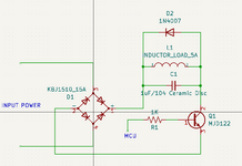
Please see the picture that is attached.

The load may be turned ON/OFF with a 100ms delay based on the controller's signal.
Instead of a mechanical relay, we used an NPN transistor.
It is now operating OK, however the bridgre rectifier temperature is occasionally rising when the load is switched ON
How can I fix the heating problem on the rectifier?
 

Attachments

  • Reference Image.png
    Reference Image.png
    25.1 KB · Views: 94

You have a heatsink on rectifier ?

What is the rate at which the switch, NPN, is operated ?

What is the line input V to the bridge ? 110 or 220 Vac ?

You sure the 1N4007 is still working correctly ? Maybe post some
pics from oscilloscope measured across the bridge output. Be careful
and do differential measurements, follow this ap note so you do not
blow up your scope ::


A 1N4007 is not exactly a fast rectifier for motor back emf suppression applications.

You are using a Darlington for a switch, that creates a lot of power dissipation due
to its high Vcesat values. And it is a slow switch, its switching times also quite high.

Regards, Dana.
 
Last edited:

The input will be 12VDC or 24VDC.
NPN operating time will be 100ms between ON and OFF condition.
Shall we use fast recovery diodes instead of 1N4007.?
 

Hi,

you are a long term member here.

Don´t want to be offensive, but your question is like from a newbie.

* R, L, C and D are most the most basic electronic devices. You should be aware of how they work.

* Also you should know some basic equations in electronics, like for power: P = V x I.
Thus you should know that you need to give some values for V and I ...

* Also your schematic is far from being complete. No input voltage, frequency, waveform. No MCU signal voltage and no information what is the common reference (GND).

* The description lacks of many infromations
This sentence leads to more questions than true information. "may", "delay", "based on"...
The load may be turned ON/OFF with a 100ms delay based on the controller's signal.


How can I fix the heating problem on the rectifier?
Since "heating" means temperature rise ... and temperature rise is delta_T = P_D * R_th..
So the answer is rather clear: o reduce the temperature rise you have to
* reduce P, by reducing V or I or both
* reduce R_th by installing a heatsink.

* you talk about relay and transistor ... but your final question does not even depend on whether you use the one or the other.

***
Nowadys we have the internet. It provides many many tutorials, especiall for the basic stuff. But also vor very advanced stuff. And we also have youtube for a most effective way of teaching things (compared to pure text).

To speed up your designs in the future, it could be rather effective to watch some youtube tutorials for basic electronic stuff. The earlier the better.


Klaus
--- Updated ---

added:
The input will be 12VDC or 24VDC.
NPN operating time will be 100ms between ON and OFF condition.
Shall we use fast recovery diodes instead of 1N4007.?
DC? Then, what is the rectifier for?
Please give clear informations: How long is the ON_time, how long is the OFF_time?

Diode:
* most important: V and I
* do you know what "fast recovery" means?
The "recovery" comes into play when
* there is current through a diode (supplied by the L)
* and - at the same time - the BJT becomes switched ON with high dI/dt.
--> thus there are two questions - your schematic and your text does not provide:
* what´s the expected dI/dt of your BJT.
* and how likely is it that - at the "ON-edge" of the BJT - the inductor still provides current for the diode to stay conductive?

Klaus
 
Last edited:

The input will be 12VDC or 24VDC.
NPN operating time will be 100ms between ON and OFF condition.
Shall we use fast recovery diodes instead of 1N4007.?

Why the bridge then ? If power is DC input ?

Fast recovery, scope shots will tell you that. But general practice, especially
when there are motor levels of current involved, yes to fast recovery.


Regards, Dana.
 

Less load current, lower rectifier losses @ load, or better
heat removal.

A pure inductor load does not limit current except if you
control on-time. You might be interested in whether the
NPN / Darlington is turning off as quickly as you imagine
(or getting so cooked that its turnoff time blows way out,
and beware any Darlington that does not give you access
to the lower base / upper emitter, to enable adjusting that).
 

Hello buddy, your filter capacitor seems to be installed incorrectly. It does not store energy when the NPN transistor is not turned on. As for the bridge heating, it should be a reverse end recovery time issue. You can connect a high-speed rectifier tube in series at the positive pole of the rectifier bridge.
 

Status
Not open for further replies.

Similar threads

Part and Inventory Search

Welcome to EDABoard.com

Sponsor

Back
Top