Continue to Site

Welcome to EDAboard.com

Welcome to our site! EDAboard.com is an international Electronics Discussion Forum focused on EDA software, circuits, schematics, books, theory, papers, asic, pld, 8051, DSP, Network, RF, Analog Design, PCB, Service Manuals... and a whole lot more! To participate you need to register. Registration is free. Click here to register now.

[SOLVED] Controlling an LCD via a port expander

Status
Not open for further replies.

Elyments

Junior Member level 3
Joined
Apr 11, 2010
Messages
31
Helped
1
Reputation
2
Reaction score
1
Trophy points
1,288
Location
Cambridge, UK
Activity points
1,493
Hi, I am using the PICDEM PIC18 Explorer with the PIC18f8722 micro. It connects to its LCM-S01602 DTR/m display via the MCP23S17 port expander. I am using the mikroC PRO compiler for programming.

Here is my code:

Code:
// Port Expander module connections
sbit  SPExpanderRST at RF6_bit;
sbit  SPExpanderCS  at RA2_bit;
sbit  SPExpanderRST_Direction at TRISF6_bit;
sbit  SPExpanderCS_Direction  at TRISA2_bit;
// End Port Expander module connections

void main() {

CMCON = 0x07;  // turn off comparators
ADCON1 = 0x3f; // set analog pins to digital I/O

SPI1_Init();

  SPI_Lcd8_Config(0);                     // Initialize Lcd over SPI interface
  SPI_Lcd8_Cmd(_LCD_CLEAR);               // Clear display
  SPI_Lcd8_Cmd(_LCD_CURSOR_OFF);          // Turn cursor off
  SPI_Lcd8_Out(1,3, "HELLO");            // Print text to Lcd, 1st row, 3rd column

}

When I program my PIC nothing is shown on the LCD, does anyone know why this is happening?

Thanks in advance,
Ely
 

I don't see, that you setup the pin configuration according to the mikroC manual. Apparently you're not using the default pin assignments for the expander interface, then the assignment expected to be specified with the SPI_Lcd8_Config() command.
 
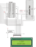
Hi, thanks for the reply. I'm unsure what you mean. Here is the example schematic from mikroC PRO help files.

scheme_spi_lcd8.gif

The only difference between that and my own is that I have used PIC18f8722 and different ports.
 

I'm unsure what you mean.
According to the manual, rst and cs pins need to be specified.
Code:
void Spi_Lcd8_Config(char DeviceAddress, unsigned char * rstport, unsigned char rstpin, unsigned char * csport, unsigned char cspin);

Initializes LCD via SPI interface with pin settings (Reset pin and Chip Select pin) you specify.
 

Both of those pins are specified as here:
Code:
// Port Expander module connections
sbit  SPExpanderRST at RF6_bit;
sbit  SPExpanderCS  at RA2_bit;
sbit  SPExpanderRST_Direction at TRISF6_bit;
sbit  SPExpanderCS_Direction  at TRISA2_bit;
// End Port Expander module connections
 

FvM, I think you are referring to older versions of mikroC. In the newer mikroC PRO for PIC versions, they are configured as Elyments has shown. The corrected code is:
Code:
// Port Expander module connections
sbit  SPExpanderRST at RF6_bit;
sbit  SPExpanderCS  at RA2_bit;
sbit  SPExpanderRST_Direction at TRISF6_bit;
sbit  SPExpanderCS_Direction  at TRISA2_bit;
// End Port Expander module connections

void main() {

     CMCON = 0x07;  // turn off comparators
     ADCON1 = 0x3f; // set analog pins to digital I/O

     SPI1_Init();

     SPI_Lcd8_Config(0);                     // Initialize Lcd over SPI interface
     SPI_Lcd8_Cmd(_LCD_CLEAR);               // Clear display
     SPI_Lcd8_Cmd(_LCD_CURSOR_OFF);          // Turn cursor off
     SPI_Lcd8_Out(1,3, "HELLO");            // Print text to Lcd, 1st row, 3rd column

     while(1);

}

I just added the while(1); line. This makes the microcontroller continuously loop over there. Unless you do that, the microcontroller does the job then goes back, restarts operations, undergoes all initialization, etc. You need to prevent the microcontroller from doing that.

I hope you made the necessary changes to the hardware.

Hope this helps.
Tahmid.
 
Hi Tahmid, thanks for your reply. I added the while(1); line but still nothing is seen on the display when I program it. I cannot yet find the problem!
 

Did you set the configuration bits properly? Did you adjust the pot (Contrast Adjustment)? Did you make the necessary changes in the hardware? Did you connect RST to RF6 and CS to RA2 instead of how they are shown in the mikroC example file?
 

RST is connected to RF6 and CS to RA2 so that part is ok.

There is no pot on this demo board to adjust contrast and the configuration bits are set in the code.

What do you mean by the necessary changes in the hardware?
 

A fixed contrast voltage of reasonable value would be O.K. as well.

Did you connect the SPI1 lines (SCK1, SDO1,SDI1) correctly?
Did you check, if SPI_Lcd8_Config(0) or the succeding commands change the level on any port expander output?
The ultimate test method would be either probing SPI respectively LCD line with a digital storage oscilloscope or logic analyzer. Or single stepping the code with a debug adapter in MPLAB.
 

The configuration bits are set from Project > Edit Project. But I think you already know this.
What did you set for the oscillator? What is the oscillator frequency?
Does your hardware match the selected oscillator mode. If you selected HS or XT, did you use a crystal oscillator or resonator of the correct frequency?

---------- Post added at 21:54 ---------- Previous post was at 21:51 ----------

Did you connect pin9 (RG5 / MCRL) to +5v? Or did you disable MCLR?
 

Hi, I can successfully program the port expander on its own so I think the problem is with the SPI_Lcd8_Config() command. I am wondering if this LCD display is controllable via this library?
 

Possibly not.

While there are several LCD controllers which claim to be HD44780 compatible, many have subtle differences in timing and delay requirements.

And unfortunately this illustrates one of the major problems with the MikroC Library Functions, without access to the source you can never be sure what is going on behind the scenes.

You might want to try adding a 20ms delay before call the LCD initialization routine, most LCDs require between 10ms and 20ms to run through their powerup cycle after voltage has stabilized to a required level. Any attempt to issue commands to the LCD before that point will result in improper initialization and operation of the LCD.

BigDog

---------- Post added at 19:18 ---------- Previous post was at 19:10 ----------

Are you using an LCD with HD44780 controller?

The Lumex LCM-S01602 DTR/M does not specific the controller use in their display in any of their documentation.

And from personal experience, does suffer from certain timing issues.
 
Tahmid, the display is a LCM-S01602 DTR/m, I cant find anywhere that says whether it is compatible.

BigDog, thanks for the idea; I added the delay but still nothing on the screen.
 

Yes the Lumex LCM-S01602 DTR/M can be finicky. I'll got close to a dozen on various Microchip dev boards here.

Have you thought about using the MikroC port expander channel with the LCD delay and command sequences from Microchip's demo program for that board?

By the way, what exactly are you getting on the display?

BigDog
 

There is a back light on the display but no text. The demo program for the board is written in assembly so I don't know how I can use this in mikroC.
 

There is a back light on the display but no text. The demo program for the board is written in assembly so I don't know how I can use this in mikroC.

Sounds like the LCD is not being initialized properly. I'll see if I can find some C18 or PICC18 code for the Explorer PIC18 board using the display.

Do you think you could pipe commands through the SPI expander channel setup by the MikroC library?

BigDog
 

That's very kind of you!

Hopefully if the C18 code is simple enough for me to understand I can send the commands the mirkroC way!
 

Status
Not open for further replies.

Similar threads

Part and Inventory Search

Welcome to EDABoard.com

Sponsor

Back
Top