Continue to Site

Welcome to EDAboard.com

Welcome to our site! EDAboard.com is an international Electronics Discussion Forum focused on EDA software, circuits, schematics, books, theory, papers, asic, pld, 8051, DSP, Network, RF, Analog Design, PCB, Service Manuals... and a whole lot more! To participate you need to register. Registration is free. Click here to register now.

[SOLVED] Controlling 12V DC Motor with FPGA

Status
Not open for further replies.

liamv

Newbie level 3
Joined
Jul 4, 2012
Messages
3
Helped
0
Reputation
0
Reaction score
0
Trophy points
1,281
Activity points
1,300
Hi long story short I want to control a simple 3-18V DC Motor using the output pins from my UP1 FLEX10K board.

I have the VHDL code ready to go but obviously the board only outputs a 5V High, idaelly i need 12V dor the motor application.

The motor has a maximum current draw of 600 mA, is this too much to say, code the board to connect pins A (12v reg) and B (motor positive) to switch it on?

Should I use a darlington array?

Thanks for your help
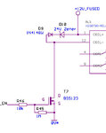
 

Hi, I don't know what the outputs of your board can handle, but assuming it is simple logic outputs with not much
current supplying capability, then you do need a circuit. Anyway, this is a reasonable way to do it (and it
would work for 3.3v logic levels too). Replace the "coil" with the motor. Replace the BSS138 with something like FDN335N.
Don't include the zener and just replace it with a wire (otherwise you'd need a slightly lower voltage zener).
When EN goes high, the motor would turn on. I tend to keep lots of MOSFETs so I prefer this method personally, but darlington
would work too.
control.jpg
 

Hi, I don't know what the outputs of your board can handle, but assuming it is simple logic outputs with not much
current supplying capability, then you do need a circuit. Anyway, this is a reasonable way to do it (and it
would work for 3.3v logic levels too). Replace the "coil" with the motor. Replace the BSS138 with something like FDN335N.
Don't include the zener and just replace it with a wire (otherwise you'd need a slightly lower voltage zener).
When EN goes high, the motor would turn on. I tend to keep lots of MOSFETs so I prefer this method personally, but darlington
would work too.
View attachment 76764


Thanks for your reply, it's a great start; forgot to tell you it needs to be reversible (polarities). This was an easy task with logic circuit outputs, but now I think its going to take about four MOSFETs or something similar now. Maybe I'll post it back here when I get it working.
Is the 1N Diode in your schematic also necessary or can I just route the negative motor terminal straight to the top of the Mosfet?
 

Status
Not open for further replies.

Part and Inventory Search

Welcome to EDABoard.com

Sponsor

Back
Top