Continue to Site
Follow along with the video below to see how to install our site as a web app on your home screen.
Note: This feature may not be available in some browsers.
/*
* Author :
    Reza F
*/

//*----------------------------------------------
//Configurations and Functions
//*----------------------------------------------

// LCD module connections
sbit LCD_RS at RC4_bit;
sbit LCD_EN at RC5_bit;
sbit LCD_D4 at RC0_bit;
sbit LCD_D5 at RC1_bit;
sbit LCD_D6 at RC2_bit;
sbit LCD_D7 at RC3_bit;

sbit LCD_RS_Direction at TRISC4_bit;
sbit LCD_EN_Direction at TRISC5_bit;
sbit LCD_D4_Direction at TRISC0_bit;
sbit LCD_D5_Direction at TRISC1_bit;
sbit LCD_D6_Direction at TRISC2_bit;
sbit LCD_D7_Direction at TRISC3_bit;
// End LCD module connections

char txt1[] = "Reza F";
char txt2[] = "Tel Remote";
char i;                              // Loop variable
char tone[2];
char tone2[2];
char password[4];
char password2[4] = {'1','2','3','4'};
char txt[4];

void Move_Delay() {                  // Function used for text moving
  Delay_ms(500);                     // You can change the moving speed here
}

void Disconnect() {
      delay_ms(2000);
      RD3_bit = 0;                       //Disconnect - off hook relay off
}

char Decode() {
     if((RA0_bit==0) && (RA1_bit==1) && (RA2_bit==0) && (RA3_bit==1))
      {tone[1] = '0';
      return tone[1];}
     else if((RA0_bit==1) && (RA1_bit==0) && (RA2_bit==0) && (RA3_bit==0))
      {tone[1] = '1';
      return tone[1];}
     else if((RA0_bit==0) && (RA1_bit==1) && (RA2_bit==0) && (RA3_bit==0))
      {tone[1] = '2';
      return tone[1];}
     else if((RA0_bit==1) && (RA1_bit==1) && (RA2_bit==0) && (RA3_bit==0))
      {tone[1] = '3';
      return tone[1];}
     else if((RA0_bit==0) && (RA1_bit==0) && (RA2_bit==1) && (RA3_bit==0))
      {tone[1] = '4';
      return tone[1];}
     else if((RA0_bit==1) && (RA1_bit==0) && (RA2_bit==1) && (RA3_bit==0))
      {tone[1] = '5';
      return tone[1];}
     else if((RA0_bit==0) && (RA1_bit==1) && (RA2_bit==1) && (RA3_bit==0))
      {tone[1] = '6';
      return tone[1];}
     else if((RA0_bit==1) && (RA1_bit==1) && (RA2_bit==1) && (RA3_bit==0))
      {tone[1] = '7';
      return tone[1];}
     else if((RA0_bit==0) && (RA1_bit==0) && (RA2_bit==0) && (RA3_bit==1))
      {tone[1] = '8';
      return tone[1];}
     else if((RA0_bit==1) && (RA1_bit==0) && (RA2_bit==0) && (RA3_bit==1))
      {tone[1] = '9';
      return tone[1];}
     else if((RA0_bit==1) && (RA1_bit==1) && (RA2_bit==0) && (RA3_bit==1))
      {tone[1] = '*';
      return tone[1];}
     else if((RA0_bit==0) && (RA1_bit==0) && (RA2_bit==1) && (RA3_bit==1))
      {tone[1] = '#';
      return tone[1];}
}

//*----------------------------------------------
//Main - Initialization
//*----------------------------------------------

void main() {

 CCP1CON = 0x00;                       // turn off comparators
 ADCON1 |= 0x07;                      // turn off analog inputs

 TRISC0_bit = 0;           //output - LCD
 TRISC1_bit = 0;
 TRISC2_bit = 0;
 TRISC3_bit = 0;
 TRISC4_bit = 0;
 TRISC5_bit = 0;
 PORTC = 0xFF;

 TRISA0_bit = 1;           //input - MT8870 and Ring
 TRISA1_bit = 1;
 TRISA2_bit = 1;
 TRISA3_bit = 1;
 TRISA4_bit = 1;
 TRISA5_bit = 1;


 TRISD0_bit = 0x00;           //output (Relays)
 TRISD1_bit = 0x00;
 TRISD2_bit = 0x00;
 TRISD3_bit = 0x00;

 TRISD6_bit = 0x00;           //output (BEEP)
 TRISE = 1;

 PORTD = 0;                  //Relays off (active high)

 RD6_bit = 0;                //Beep off

 i = 1;                              // Loop variable
 tone[1] = 0;
 tone2[1] = 0;

 Lcd_Init();                // Initialize LCD
 Sound_Init(&PORTD, 6);
 UART1_Init(9600);          // Initialize UART module at 9600 bps
 Delay_ms(100);

 Lcd_Cmd(_LCD_CLEAR);                // Clear display
 Lcd_Cmd(_LCD_CURSOR_OFF);           // Cursor off
 Lcd_Out(1,4,txt1);                 // Write text in first row
 Lcd_Out(2,1,txt2);                 // Write text in second row

 UART1_Write_Text("\r");
 UART1_Write_Text("\n");
 Delay_ms(1000);

//*----------------------------------------------
//Main - Body
//*----------------------------------------------
do{
  if(RA5_bit == 0)                      //Ring Detect
   {
    delay_ms(1000);
    Lcd_Cmd(_LCD_CLEAR);                // Clear display
    RD3_bit = 1;                        //off hook relay on (Line Connect)
   }
  if (RA4_bit == 1)                    //STD is high (new number is ready in output of MT8870)
     {
       tone2[1] = Decode();
   switch(tone2[1]){
    case '0':                 //Number 0 selected
      Lcd_Out(1,1,"0");
      break;
    case '1':                //Number 1 selected
      RD0_bit = 1;
      Lcd_Out(1,2,"1");
      Lcd_Out(2,1,"Relay 1 Active");
      break;
    case '2':                //Number 2 selected
      RD1_bit = 1;
      Lcd_Out(1,3,"2");
      Lcd_Out(2,1,"Relay 2 Active");
      break;
    case '3':
      RD2_bit = 1;
      Lcd_Out(1,4,"3");
      Lcd_Out(2,1,"Relay 3 Active");
      break;
    case '4':
      RD0_bit = 0;
      Lcd_Out(1,5,"4");
      Lcd_Out(2,1,"Relay 1 Deactivate");
      break;
    case '5':
      RD1_bit = 0;
      Lcd_Out(1,6,"5");
      Lcd_Out(2,1,"Relay 2 Deactivate");
      break;
    case '6':
      RD2_bit = 0;
      Lcd_Out(1,7,"6");
      Lcd_Out(2,1,"Relay 3 Deactivate");
      break;
    case '7':
      Lcd_Out(1,8,"7");
      break;
    case '8':
      Lcd_Out(1,9,"8");
      break;
    case '9':
      Lcd_Out(1,10,"9");
      break;
    case '*':
      Lcd_Out(1,11,"*");
      break;
    case '#':
      Lcd_Out(1,12,"#");
      Disconnect();
      delay_ms(3000);
      Lcd_Cmd(_LCD_CLEAR);
      Lcd_Out(1,4,txt1);                 // Write text in first row
      Lcd_Out(2,1,txt2);                 // Write text in second row
      break;
    }
  }
}while(1);
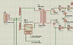
}Thanks luben111 . I make the PCB of this project and assembled and take best answer from that with a few changes that I attached in a new PDF file and the C code for use of other friends.:smile: the only problem is that the volum of beep sound is very low.:sad: I insert +5 on the RD6 pin of PIC for beep sound.
below is the code I written for this project(this code worked correctly but can be improved yet):
Code:/* * Author : Reza F */ //*---------------------------------------------- //Configurations and Functions //*---------------------------------------------- // LCD module connections sbit LCD_RS at RC4_bit; sbit LCD_EN at RC5_bit; sbit LCD_D4 at RC0_bit; sbit LCD_D5 at RC1_bit; sbit LCD_D6 at RC2_bit; sbit LCD_D7 at RC3_bit; sbit LCD_RS_Direction at TRISC4_bit; sbit LCD_EN_Direction at TRISC5_bit; sbit LCD_D4_Direction at TRISC0_bit; sbit LCD_D5_Direction at TRISC1_bit; sbit LCD_D6_Direction at TRISC2_bit; sbit LCD_D7_Direction at TRISC3_bit; // End LCD module connections char txt1[] = "Reza F"; char txt2[] = "Tel Remote"; char i; // Loop variable char tone[2]; char tone2[2]; char password[4]; char password2[4] = {'1','2','3','4'}; char txt[4]; void Move_Delay() { // Function used for text moving Delay_ms(500); // You can change the moving speed here } void Disconnect() { delay_ms(2000); RD3_bit = 0; //Disconnect - off hook relay off } char Decode() { if((RA0_bit==0) && (RA1_bit==1) && (RA2_bit==0) && (RA3_bit==1)) {tone[1] = '0'; return tone[1];} else if((RA0_bit==1) && (RA1_bit==0) && (RA2_bit==0) && (RA3_bit==0)) {tone[1] = '1'; return tone[1];} else if((RA0_bit==0) && (RA1_bit==1) && (RA2_bit==0) && (RA3_bit==0)) {tone[1] = '2'; return tone[1];} else if((RA0_bit==1) && (RA1_bit==1) && (RA2_bit==0) && (RA3_bit==0)) {tone[1] = '3'; return tone[1];} else if((RA0_bit==0) && (RA1_bit==0) && (RA2_bit==1) && (RA3_bit==0)) {tone[1] = '4'; return tone[1];} else if((RA0_bit==1) && (RA1_bit==0) && (RA2_bit==1) && (RA3_bit==0)) {tone[1] = '5'; return tone[1];} else if((RA0_bit==0) && (RA1_bit==1) && (RA2_bit==1) && (RA3_bit==0)) {tone[1] = '6'; return tone[1];} else if((RA0_bit==1) && (RA1_bit==1) && (RA2_bit==1) && (RA3_bit==0)) {tone[1] = '7'; return tone[1];} else if((RA0_bit==0) && (RA1_bit==0) && (RA2_bit==0) && (RA3_bit==1)) {tone[1] = '8'; return tone[1];} else if((RA0_bit==1) && (RA1_bit==0) && (RA2_bit==0) && (RA3_bit==1)) {tone[1] = '9'; return tone[1];} else if((RA0_bit==1) && (RA1_bit==1) && (RA2_bit==0) && (RA3_bit==1)) {tone[1] = '*'; return tone[1];} else if((RA0_bit==0) && (RA1_bit==0) && (RA2_bit==1) && (RA3_bit==1)) {tone[1] = '#'; return tone[1];} } //*---------------------------------------------- //Main - Initialization //*---------------------------------------------- void main() { CCP1CON = 0x00; // turn off comparators ADCON1 |= 0x07; // turn off analog inputs TRISC0_bit = 0; //output - LCD TRISC1_bit = 0; TRISC2_bit = 0; TRISC3_bit = 0; TRISC4_bit = 0; TRISC5_bit = 0; PORTC = 0xFF; TRISA0_bit = 1; //input - MT8870 and Ring TRISA1_bit = 1; TRISA2_bit = 1; TRISA3_bit = 1; TRISA4_bit = 1; TRISA5_bit = 1; TRISD0_bit = 0x00; //output (Relays) TRISD1_bit = 0x00; TRISD2_bit = 0x00; TRISD3_bit = 0x00; TRISD6_bit = 0x00; //output (BEEP) TRISE = 1; PORTD = 0; //Relays off (active high) RD6_bit = 0; //Beep off i = 1; // Loop variable tone[1] = 0; tone2[1] = 0; Lcd_Init(); // Initialize LCD Sound_Init(&PORTD, 6); UART1_Init(9600); // Initialize UART module at 9600 bps Delay_ms(100); Lcd_Cmd(_LCD_CLEAR); // Clear display Lcd_Cmd(_LCD_CURSOR_OFF); // Cursor off Lcd_Out(1,4,txt1); // Write text in first row Lcd_Out(2,1,txt2); // Write text in second row UART1_Write_Text("\r"); UART1_Write_Text("\n"); Delay_ms(1000); //*---------------------------------------------- //Main - Body //*---------------------------------------------- do{ if(RA5_bit == 0) //Ring Detect { delay_ms(1000); Lcd_Cmd(_LCD_CLEAR); // Clear display RD3_bit = 1; //off hook relay on (Line Connect) } if (RA4_bit == 1) //STD is high (new number is ready in output of MT8870) { tone2[1] = Decode(); switch(tone2[1]){ case '0': //Number 0 selected Lcd_Out(1,1,"0"); break; case '1': //Number 1 selected RD0_bit = 1; Lcd_Out(1,2,"1"); Lcd_Out(2,1,"Relay 1 Active"); break; case '2': //Number 2 selected RD1_bit = 1; Lcd_Out(1,3,"2"); Lcd_Out(2,1,"Relay 2 Active"); break; case '3': RD2_bit = 1; Lcd_Out(1,4,"3"); Lcd_Out(2,1,"Relay 3 Active"); break; case '4': RD0_bit = 0; Lcd_Out(1,5,"4"); Lcd_Out(2,1,"Relay 1 Deactivate"); break; case '5': RD1_bit = 0; Lcd_Out(1,6,"5"); Lcd_Out(2,1,"Relay 2 Deactivate"); break; case '6': RD2_bit = 0; Lcd_Out(1,7,"6"); Lcd_Out(2,1,"Relay 3 Deactivate"); break; case '7': Lcd_Out(1,8,"7"); break; case '8': Lcd_Out(1,9,"8"); break; case '9': Lcd_Out(1,10,"9"); break; case '*': Lcd_Out(1,11,"*"); break; case '#': Lcd_Out(1,12,"#"); Disconnect(); delay_ms(3000); Lcd_Cmd(_LCD_CLEAR); Lcd_Out(1,4,txt1); // Write text in first row Lcd_Out(2,1,txt2); // Write text in second row break; } } }while(1); }
Decrease input resistor value for signal to make signal stronger.the only problem is that the volum of beep sound is very low.