Continue to Site

Welcome to EDAboard.com

Welcome to our site! EDAboard.com is an international Electronics Discussion Forum focused on EDA software, circuits, schematics, books, theory, papers, asic, pld, 8051, DSP, Network, RF, Analog Design, PCB, Service Manuals... and a whole lot more! To participate you need to register. Registration is free. Click here to register now.

Control direction of motor by different voltage levels.

neazoi

Advanced Member level 6
Joined
Jan 5, 2008
Messages
4,123
Helped
13
Reputation
26
Reaction score
15
Trophy points
1,318
Location
Greece
Activity points
36,955
I would like to control the direction of a small (toy) DC motor by applying different voltage levels to it.
The motor is to be used on an outdoors rotor.
The rotor will control the direction of a small magnetic loop antenna.
There will be an RF preamplifier for the loop near the loop.
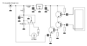
The whole system will be powered and controlled through the coaxial cable only.

The idea is to have say 12v present at the coaxial all the time. At this time, the motor will be off. When for example 15v is present at the coaxial, the motor will turn clockwise. When for example 24v is present at the coaxial, the motor will turn anti-clockwise.

Obviously the RF preamplifier will have an onboard regulator which will stabilize these higher voltages to 12v needed by the preamplifier.

So there will be 3 states
1. 12v, the RF preamplifier is on.
2. 15v (example) the RF preamplifier is on and the motor rotates clockwise.
3. 24v (example) the RF preamplifier is on and the motor rotates anti-clockwise.

I would love to do that using discrete circuits.

Maybe a simple DPDT 24v relay?
 

    neazoi

    Points: 2
    Helpful Answer Positive Rating
all the time 12V ...


how can it be while all the time there is 12V?
Is there a second coax?

I´m a bit confused.

Klaus
Yes, I am talking about feeding the preamplifier with 12v. Then the voltage is increased for the rotations of the motor of course. As long as the motor does not need to be rotated, the voltage falls back to 12v again.
 
Easy with ICs, doable with discrete components.
You need a good RF isolation filter to keep the DC and RF apart, a 12V regulator to power the pre-amp and something to detect 15V and 24V. The voltage detectors could be say a 13V and 22V Zener diodes with pull-down resistors to ground and series resistors from the junctions to the bases of two transistors. The transistors would both be non-conducting at 12V, one conducting at 15V and both conducting at 24V. From there drive a bridge circuit with the motor across the bridge arms.

An alternative approach would be a proportional control circuit as used on radio controlled models. The motor driver running from say 12V all the time but higher voltage pulses on the co-ax deciding the actual motor voltage and polarity.

Personally, I would use a stepper motor with a limit switch, it allows absolute rotation angle and prevents the rig being dragged through the window as the cable winds itself around the mast :)

Brian.
HIHI!
Ok, I understood the idea about the zeners and the transistors circuit.
Meanwhile, I was also thinking of a simple relay circuit, attached.
It works like this. When there is 12v in the line, the 24v relay cannot actuate and only the preamp is fed with 9v through the regulator.
Rx lowers down the voltage (current) too much and the motor is off.
As the voltage is increased, there will be a point where the Rx would cause a larger voltage to the motor and the motor will turn in one direction.
As the voltage is increased more, the relay will actuate and the direction of the rotation will be altered.

Rx needs to be found experimentically and it might be a good idea to put a pair of series, opposite polarity zeners in series with the Rx, as a bidirectional motor voltage regulator. Or maybe not.

What do you think?
 

Attachments

  • motor.JPG
    motor.JPG
    50 KB · Views: 25
... but check the 'bias T' works over the bandwidth you need and can carry enough current.

Perhaps a simpler alternative is to simply add back to back Zeners in series with the motor so it doesn't operate until >12V is present then reverse the polarity to change motor direction. A bridge rectifier ahead of the regulator could keep the polarity constant for the pre-amp.

Might be worth looking up "Diseqc", a system used to motorised dish antennas for ideas.

Brian.
 

LaTeX Commands Quick-Menu:

Part and Inventory Search

Welcome to EDABoard.com

Sponsor

Back
Top